Installation Instructions PowerMonitor 1000 Unit Catalog Numbers 1408-TR1A-485, 1408-TR2A-485, 1408-EM1A-485, 1408-EM2A-485, 1408-EM3A-485, 1408-TR1A-ENT, 1408-TR2A-ENT, 1408-EM1A-ENT, 1408-EM2A-ENT, 1408-EM3A-ENT Topic Page Important User Information 2 Safety 3 About the PowerMonitor 1000 Unit 3 PowerMonitor 1000 Unit Features and Functions 3 Catalog Number Explanation 7 Before You Begin 7 Mount the PowerMonitor 1000 Unit 8 Wire the PowerMonitor 1000 Unit 10 Set Up the PowerMonitor 1000
PowerMonitor 1000 Unit Important User Information Read this document and the documents listed in the additional resources section about installation, configuration, and operation of this equipment before you install, configure, operate, or maintain this product. Users are required to familiarize themselves with installation and wiring instructions in addition to requirements of all applicable codes, laws, and standards.
PowerMonitor 1000 Unit 3 Safety ATTENTION: Only qualified personnel, following accepted safety procedures, should install, wire, and service the PowerMonitor™ 1000 unit and its associated components. Before beginning any work, disconnect all sources of power and verify that they are de-energized and locked out. Failure to follow these instructions may result in personal injury or death, property damage, or economic loss.
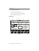
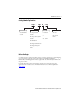
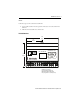
PowerMonitor 1000 Unit The power monitor family includes five models: • • • • • TR1 – Voltage and current transducer TR2 – Voltage, current, and power transducer EM1 – Basic real-energy monitor for sub-metering applications EM2 – Energy and demand monitor for main metering applications EM3 – Full-function power and energy monitor Hardware Features 1 3 2 EtherNet/IP RS-485 4 5 RS-485 RX TX STATIS Mod 6 PowerMonitor 1000 Net + - SHLD ACT 7 LNK 8 9 10 Rockwell Automation Publication 140
PowerMonitor 1000 Unit 5 Feature Description 1. Ethernet network port - standard RJ-45 jack with status indicators Ethernet network port hardware is included on all models. The port functions only on units ordered with or upgraded to the Ethernet network. The following protocols and functions are supported.
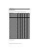
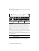
PowerMonitor 1000 Unit Functionality by Model The power monitor models differ by the data sets available to client applications. This table indicates the measurements and functions available in each model.
PowerMonitor 1000 Unit 7 Catalog Number Explanation 1408 - TR1 A - 485 Bulletin Number Functionality Control Power Communication 1408 - PowerMonitor 1000 Unit TR1 - Voltage and current transducer A - 120/240V AC 485 - Serial or ENT - Serial and Ethernet TR2 - Voltage, current, and power transducer 125…250V DC EM1 - KWh submeter EM2 - Energy and demand monitor EM3 - Energy, demand, power monitor Before You Begin Use this document as a guide for installing, wiring, connecting, applying power,
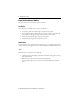
PowerMonitor 1000 Unit Mount the PowerMonitor 1000 Unit The power monitor can be mounted on a panel or a DIN rail. Panel Mount Follow these steps to mount the unit on a panel or any flat surface. 1. Extend the top and bottom DIN rail clips to the panel mount position. 2. Insert a small screwdriver under the spring pin to move the clip, lift it, and pull the clip forward until it extends approximately 6 mm (0.25 in.) from the enclosure. 3. Release the pin and lock the clip in the panel mount position. 4.
PowerMonitor 1000 Unit 9 Remove Follow these steps to remove the unit from a DIN rail. 1. Insert a small screwdriver into the exposed slot in the tab to remove the unit from the DIN rail. 2. Pull enclosure forward and remove from the rail. Product Dimensions 140 (5.5) 70 (2.78) EtherNet/IP RS-485 RS-485 RX 90 (3.54) STATIS PowerMonitor 1000 TX Mod Net + - SHLD ACT LNK All dimensions are mm (in.). Panel mount depth 59 mm (2.4 in.). DIN-rail mount depth 62 mm (2.44 in.).
PowerMonitor 1000 Unit Wire the PowerMonitor 1000 Unit The power monitor has finger-safe screw terminals with pressure plates for all wiring connections. Terminal Block Layout V1 V3 V2 VN I1+ I2+ I3+ S1 I1- I2- I3- NC S2 SCOM L1 L2 CF1 Y K CF Z Wire Type Wire Size Range Wires per Terminal Recommended Torque Cu - 75 °C (167 °F) 0.33…0.21 mm2 (22 … 14 AWG) 2 max per terminal, sol-sol or str-str only (no mixed pairs) 0.
PowerMonitor 1000 Unit 11 Three-phase, Four-wire Wye, Direct Connect (600V AC Line-to-line, 347V AC Line-to-neutral Maximum) Line L1 L2 L3 N Voltage Mode = Wye PowerMonitor 1000 Unit Fuses (by user) V1 V2 V3 VN Load Three-phase, Three-wire Grounded Wye, Direct Connect (600V AC Line-to-line, 347V AC Line-to-neutral Maximum) Line L1 L2 L3 Voltage Mode = Wye PowerMonitor 1000 Unit Fuses (by user) V1 V2 V3 VN Ground Load Rockwell Automation Publication 1408-IN001E-EN-P - September 2013
PowerMonitor 1000 Unit Three-phase, Four-wire Wye with Potential Transformers Line L1 L2 L3 Voltage Mode = Wye N PowerMonitor 1000 Unit Fuses (by user) PTs (by user) V1 V2 V3 VN Ground Ground Load Three-phase, Three-wire Grounded Wye with Potential Transformers Line L1 L2 L3 Voltage Mode = Wye PowerMonitor 1000 Unit PTs (by user) Fuses (by user) V1 V2 V3 VN Ground Load Ground Ground Rockwell Automation Publication 1408-IN001E-EN-P - September 2013
PowerMonitor 1000 Unit 13 Three-phase, Three-wire Open Delta with Two Potential Transformers Line L1 L2 Voltage Mode = Open Delta L3 PowerMonitor 1000 Unit Fuses (by user) PTs (by user) V1 V2 V3 VN Ground Ground Load Single-phase, Direct Connect (600V AC Line-to-line, 347V AC Line-to-neutral Maximum) Line L1 L2 N Voltage Mode = Single Phase PowerMonitor 1000 Unit Fuses (by user) V1 V2 V3 VN Load Rockwell Automation Publication 1408-IN001E-EN-P - September 2013
PowerMonitor 1000 Unit Single-phase with Potential Transformers Line L1 L2 Voltage Mode = Single Phase N PowerMonitor 1000 Unit Fuses (by user) PTs (by user) V1 V2 V3 VN Ground Ground Load Three-phase, Three-wire Delta, Direct Connect (600V AC Line-to-line, 347V AC Line-to-ground Maximum) Line L1 L2 L3 Voltage Mode = Delta Direct PowerMonitor 1000 Unit Fuses (by user) V1 V2 V3 VN Ground Load Rockwell Automation Publication 1408-IN001E-EN-P - September 2013
PowerMonitor 1000 Unit 15 Maximum line to ground voltage is 347V. If line to ground voltage exceeds 347V, then potential transformers must be used. The unit indicates voltage overrange (999.0) if an intentional or accidental ground causes line to ground voltage in excess of 347V.
PowerMonitor 1000 Unit Three-phase, Three- or Four-wire, Three-current Transformers Line L1 L2 L3 N (if used) Voltage Mode = Any PowerMonitor 1000 Unit Shorting Terminal Block (by user) I1+ I1I2+ CTs (by user) I2I3+ I3- Load Ground Three-phase, Three-wire, Two-current Transformers Line L1 L2 Voltage Mode = Any L3 PowerMonitor 1000 Unit Shorting Terminal Block (by user) I1+ I1I2+ CTs (by user) I2I3+ I3- Ground Load Rockwell Automation Publication 1408-IN001E-EN-P - September 2013
PowerMonitor 1000 Unit 17 You can use two CTs only on three-wire systems. Single-phase, Two-current Transformers Line L1 N L2 Voltage Mode = Any PowerMonitor 1000 Unit Shorting Terminal Block (by user) I1+ I1I2+ CTs (by user) I2I3+ I3- Load Ground Special Wiring Modes There are two special wiring modes for the power monitor. 1PT 1CT Line-to-line This special wiring mode is designed for use in capacitor bank controllers.
PowerMonitor 1000 Unit 1PT 1CT Line-to-line Line L1 L2 Voltage Mode = 1PT1CT Line-to-line L3 PowerMonitor 1000 Fuses (by user) PT (by user) V1 V2 V3 Ground VN Shorting terminal block (by user) I1+ CT (by user) I1- I2+ Load I2Ground 1PT 1CT Line-to-neutral This special wiring mode is designed for use in new capacitor bank controller installations where the legacy metering connections described in the preceding section do not apply.
PowerMonitor 1000 Unit 19 1PT and 1CT Line-to-Neutral Line L1 L2 Voltage Mode = 1PT1CT Line-to-neutral L3 PowerMonitor 1000 PT (by user, if used) Fuses (by user) V1 V2 V3 Connect to ground ONLY if PT is used VN Shorting terminal block (by user) I1+ CT (by user) I1- I2+ Load I2Ground Status Inputs One or two dry (non-powered) contacts can be connected to the power monitor status inputs. The power monitor 24V DC status input derives power from its internal power supply.
PowerMonitor 1000 Unit KYZ Output The KYZ solid-state relay output may be connected to an external pulse accumulator or controller. Wetting voltage must be provided by the external device or circuit. The KYZ output is designed for low-current (80 mA maximum) switching at up to 240V AC or 300V DC. The diagram indicates typical KYZ wiring. KYZ Output (N.C.) Z K (COM) (N.O.
PowerMonitor 1000 Unit 21 Serial Communication Use point-to-point wiring between one power monitor and a computer or other data terminal for HyperTerminal communication and DF1 full-duplex communication. DF1 half-duplex, Modbus RTU and DH-485 protocols permit a point-to-point or multi-drop network configuration. Multi-drop RS-485 communication wiring should be installed in a daisy-chain configuration. Up to 32 nodes may be connected together in a network.
PowerMonitor 1000 Unit RS-485 Point-to-point Typical Wiring RS-485 to RS-232 Converter Examples: Allen-Bradley 1761-NET-AIC (shown) B&B Electronics 485SD9TB RS-485 TERM * A + B - COM SHLD RS-485 Wiring: 2 2 /C Shielded Cable 0.
PowerMonitor 1000 Unit 23 RS-485 Multi-drop Typical Wiring RS-485 to RS-232 Converter Examples: Allen-Bradley 1761-NET-AIC (shown) B&B Electronics 485SD9TB RS-485 RS-485 A + + B - - SHLD SHLD TERM * COM RS-485 Wiring: 2 2/C Shielded Cable 0.32…4 mm (22…14 AWG) Connect A on converter to - on each PowerMonitor 1000. Connect B on converter to + on each PowerMonitor 1000. Connect shield at one end only of each link. Maximum cable length 1219 m (4000 ft.).
PowerMonitor 1000 Unit Typical Ethernet connections are shown in this diagram.
PowerMonitor 1000 Unit 25 Use Optional Software RSPower, RSPowerPlus, and RSEnergyMetrix software (with the RT option) provide configuration interfaces for the power monitor, including the ability to upload, edit, download, and back up the unit configuration on a personal computer or server. Please refer to the applicable software user documentation or help files for information on configuring the power monitor using RSPower, RSPowerPlus, or RSEnergyMetrix software.
PowerMonitor 1000 Unit The diagram and table show the LCD interface buttons and their functions. LCD Interface Up Arrow RS-485 RX TX Escape PowerMonitor 1000 STATUS Mod Net Down Arrow Enter The buttons function differently in each mode. The power monitor enters into Display mode by default.
PowerMonitor 1000 Unit 27 This diagram shows how to navigate in the display and configuration menu.
PowerMonitor 1000 Unit LCD Screen Display and Configuration Menu Map Main Menu, Page 1 Default Screen? Level 1 Display Program Password? Level 2 Display Config Setup Display Metering Level 3 Metering Volts Amps Frequency(1) Metering Power(1)(2) Metering Energy(1) PF 1 PF 2 PF 3 PF Total KW 1 KW 2 KW 3 KW Total KVAR 1 KVAR 2 KVAR 3 KVAR Total KVA 1 KVA 2 KVA 3 KVA Total Status 1 Cnt Status 2 Cnt kWH Fwd kWH Rev kWH kVARH Fwd kVARH Rev kVARH kVAH kW Demand kVAR Demand kVA Demand PF Demand kW Proj
PowerMonitor 1000 Unit 29 Default Screen The power monitor lets you select and navigate to a default screen. The default screen displays at startup and is displayed after the display has been dormant for approximately 30 minutes. To set the current screen as the default, press Enter and click Yes. If you’re in another menu and want to get back to the default screen, continue pressing Escape until you are prompted To Default Screen? Click Yes to display the default screen.
PowerMonitor 1000 Unit Setup Submenu Configuration Mode Level 2 Program Mode, Level 3 Display Mode Analog Input Advanced RS485 Ethernet New Password Date Time Meter Averaging DST Enable DST Start Month, Wk, Day DST Start Hour DST End Month, Wk, Day DST End Hour KYZ Output Select KYZ Output Scale KYZ Pulse Duration Status 1 Input Scale Status 2 Input Scale Demand Source Demand Length Demand Periods Demand Sync Delay Unit Error Action Error Log Full Action LCD Display Contrast Protocol Setting Seria
PowerMonitor 1000 Unit 31 Setup Example This example steps through setting the unit date to demonstrate use of the display and buttons to navigate through the setup menu and make changes to parameters. 1. Navigate to the initial screen. The screen shown is the top level screen. If it is not present, press until it appears. RS-485 RX TX STATUS PowerMonitor 1000 Mod Net Power And Energy Management Solutions If you press once too often, the To Default Screen? message appears.
PowerMonitor 1000 Unit 3. Press or once. Program appears in the display. Press . RS-485 RX TX STATUS PowerMonitor 1000 Mod Net Password 0000 4. Press if the password has not been changed from the default (0000). If the password has been changed, then enter the correct password. RS-485 RX TX STATUS PowerMonitor 1000 Mod Net Program Setup When the correct password is entered, Program Setup appears in the display. The power monitor is now in Program mode.
PowerMonitor 1000 Unit 33 5. Press . Analog Input appears in the display. Press . RS-485 RX TX STATUS PowerMonitor 1000 Mod Net Advanced Setup 6. With Advanced Setup displayed, press , then press until Set Date Year appears.
PowerMonitor 1000 Unit 7. Press to change the value of the year. The power monitor is now in Edit mode, indicated by the presence of the highlight cursor. Change the year value and press to save it or to discard changes. See Edit a Parameter on page 30 if you need help with this. RS-485 RX TX STATUS PowerMonitor 1000 Mod Net Set Date Year 2005 8 8. Select the next item in the configuration menu by pressing . Set the month in the same way.
PowerMonitor 1000 Unit 35 Use HyperTerminal Communication Tool to Set Up The HyperTerminal communication tool is an accessory program included with Microsoft Windows operating system. You may use the HyperTerminal communication tool to set up and view data on your power monitor as an alternative to on-device display and setup. Follow these steps to use the HyperTerminal communication tool. 1. Connect the power monitor to your computer with a serial cable. Refer to Serial Communication on page 21. 2.
PowerMonitor 1000 Unit 5. Press the Enter key three times. The following menu appears. 6. To enter a menu item, backspace to delete the default value 1, type the number of the menu item, and press Enter. In a submenu, the HyperTerminal communication tool presents parameters one at a time. To change parameter values, enter the unit password as the first parameter. To enter the password, backspace to delete the -1 and enter the correct password (0 is the default).
PowerMonitor 1000 Unit 37 9. Type N to return to the main setup menu. The HyperTerminal communication tool exits the setup menu after two minutes of inactivity. To resume, press Enter three times. Use the Web Interface You can use an Internet browser to view data and change configuration settings on your meter. Follow these steps to use the Web interface. 1.
PowerMonitor 1000 Unit 2. Click Configure Options to access the setup menus. EXAMPLE You can change the IP address of the power monitor by navigating to the Ethernet Communication screen. Enter the password, change the IP address, and save it by clicking Submit. Now you can type in the new IP address in your browser and the main page refreshes using the new address. 3. Every time you change a setting or configuration you need to enter the power monitor’s password (default = 0).
PowerMonitor 1000 Unit 39 Set-up Menus Whichever set-up method you select, set-up parameters are organized in five set-up menus. • • • • • Analog input setup Advanced setup RS-485 communication setup Optional Ethernet network communication setup Date and time setup Features This section describes in detail the functions of the power monitor. Each function includes information on set-up menus and parameters used to control its operation. Analog Input Setup This feature applies to all models.
PowerMonitor 1000 Unit Parameter Description Range Default PT secondary The secondary value of the PT ratio (Pri:Sec) indicating the nominal voltage present at the low-end of the transformer. 1…600 480 CT primary The primary value of the CT ratio (Pri:5) indicating the nominal current present at the high-end of the transformer. The nominal CT rated current is 5 A.
PowerMonitor 1000 Unit 41 • Waiting Command - five minutes have elapsed since the most recent command. • Out of Range - measured phase angles are outside the range of the selected system power factor. • Voltage or current input missing (input below the metering threshold) or inverted (reverse polarity, 180 degrees out of phase) – – – – – – – – – -1 — Test not run; see wiring status for reason. 0 — Pass, all inputs present / correct polarity. 1 — Phase 1 missing / inverted.
PowerMonitor 1000 Unit Magnitude and Phase Angle The power monitor continually returns voltage and current magnitude and phase angle data. This data may be used to construct a phasor diagram, and in addition to the diagnostics parameters, to troubleshoot wiring issues. The following exceptions apply.
PowerMonitor 1000 Unit 43 Troubleshooting Mode Troubleshooting mode lets you enter a password-protected command that makes available all metered parameters for troubleshooting purposes. Troubleshooting mode does not change the data log support. You may command your power monitor into Troubleshooting mode by using the LCD screen, the web page, the HyperTerminal interface, or via communication. You must enter a unique password to enter Troubleshooting mode.
PowerMonitor 1000 Unit RS-485 Communication This function applies to all models. Setup Your power monitor is set up to communicate via its RS-485 port using a default set of parameters when you first apply power.
PowerMonitor 1000 Unit 45 This feature applies to all models with catalog numbers ending in -ENT. The Ethernet network port supports 10 or 100 Mbps data rate, half-duplex, or full-duplex. Setup The Ethernet network port is set up with a default IP address and gateway using a common auto-configuration addressing scheme. The default address simplifies the task of making an initial connection to the unit from a personal computer with a compatible Class B IP address.
PowerMonitor 1000 Unit In this example, the NetID is 192.1.1.0 and the HostID is 0.0.0.207. The relationship between NetID and HostID depends on the IP address class, the discussion of which is beyond the scope of this document (the example uses a Class C IP address). Devices on the same subnet can communicate directly; devices on different subnets may communicate with each other only through a gateway or router.
PowerMonitor 1000 Unit 47 Commands The following commands are supported by the power monitor: • • • • Set GWh/kWh register Set GVARh/kVARh register Set GVAh/kVAh register Clear all energy registers Related Functions • KYZ output • Energy log • Configuration lock Demand Metering Demand is an electric power term that expresses the average energy usage over a period of time. The power monitor may be configured to measure demand using a fixed demand period or a sliding window.
PowerMonitor 1000 Unit Metered Parameters The power monitor calculates and returns the following demand values: • • • • • • Real power demand, kW Reactive power demand, kVAR Apparent power demand, kVA Demand power factor, percent lagging (-) or leading (+) Projected kW, kVAR, and kVA demand Demand interval elapsed time, minutes Projected demand calculates a linear projection of demand at the end of a demand interval. Demand power factor is calculated using the following formula.
PowerMonitor 1000 Unit 49 Parameter Description Range Default Demand Source (advanced setup) Selects the source of the demand end-of-interval (EOI) signal. 0 = Internal Timer 1 = Status Input 2 2 = Controller Command 3 = Ethernet Demand Broadcast Network-demand synch options are available only on units with an optional Ethernet network installed.
PowerMonitor 1000 Unit Results Demand metering results may be viewed using the following methods: • Web interface • LCD display • Communication Demand results are not available via the HyperTerminal communication tool. Commands • Controller command (EOI signal) Related Functions • Status inputs • Time of use log • Configuration lock Power Metering This function applies to catalog numbers 1408-TR1 (power factor only), 1408-TR2, and 1408-EM3.
PowerMonitor 1000 Unit 51 Magnitude and Direction of Power Quantities Pf = 0 +kVAR (import) kVARHR-F (forward) 90° (power factor lagging) (-) (power factor leading) (+) Pf = 100% -kW (export) kWH-R (reverse) II I 0° 180° III IV Pf = 100% +kW (import) kWH-F (forward) (power factor leading) (+) (power factor lagging) (-) 270° Pf = 0 -kVAR (export) kVARHR-R (reverse) Setup Only basic analog-input setup is required for power metering.
PowerMonitor 1000 Unit Voltage, Current, and Frequency Metering This function applies to catalog numbers 1408-TR1, 1408-TR2, and 1408-EM3.
PowerMonitor 1000 Unit 53 Date and Time Functions The power monitor internal clock and calendar is used in demand metering and data logging functions. A number of user-selectable options are available for synchronizing and controlling the internal clock and calendar. This function applies to all models. Date and Time Parameters • Date: Year, Month, Day • Time: Hour, Minute, Seconds, Hundredths Basic Setup Basic setup is done using the date and time setup menu.
PowerMonitor 1000 Unit Daylight-savings Time Setup Daylight-savings time (DST) setup is done in the Advanced Setup menu. If DST is enabled, the power monitor internal clock advances by one hour on the start date and hour specified, and is set back by one hour on the return date and hour specified. The defaults represent the common DST start and return date/times in use in the United States in 2006. The DST function also adjusts the network-time synch offset when used.
PowerMonitor 1000 Unit 55 Network Time Synchronization Network time synchronization is available only on units equipped with the optional Ethernet network. Set-up parameters are found in the Ethernet communication set-up menu. The power monitor updates its time from a simple network time protocol (SNTP) server or an anycast group of SNTP servers, depending on setup parameter values. Network-time synchronization set-up parameters are found in the Ethernet communication set-up menu.
PowerMonitor 1000 Unit Time Zones These are the available time zones. Choose the one for your region. Value Offset from GMT Time Zone Name Areas in Time Zone 0 GMT-12:00 Dateline Standard Time Eniwetok, Kwajalein 1 GMT-11:00 Samoa Standard Time Midway Island, Samoa 2 GMT-10:00 Hawaiian Standard Time Hawaii 3 GMT-09:00 Alaskan Standard Time Alaska 4 GMT-08:00 Pacific Standard Time Pacific Time (U.S. & Canada; Tijuana) 5 GMT-07:00 Mountain Standard Time Mountain Time (U.S.
PowerMonitor 1000 Unit 57 Value Offset from GMT Time Zone Name Areas in Time Zone 14 GMT+01:00 Central Europe Standard Time Belgrade, Bratislava, Budapest, Ljubljana, Prague Central European Standard Time Sarajevo, Skopje, Sofija, Vilnius, Warsaw, Zagreb Romance Standard Time Brussels, Copenhagen, Madrid, Paris W. Central Africa Standard Time West Central Africa W. Europe Standard Time Amsterdam, Berlin, Bern, Rome, Stockholm, Vienna E.
PowerMonitor 1000 Unit Value Offset from GMT Time Zone Name Areas in Time Zone 26 GMT+08:00 China Standard Time Beijing, Chongqing, Hong Kong, Urumqi North Asia East Standard Time Irkutsk, Ulaan Bataar Singapore Standard Time Kuala Lumpur, Singapore Taipei Standard Time Taipei W.
PowerMonitor 1000 Unit 59 Logged Parameters Energy log records contain a date/time stamp and the metering parameters listed below.
PowerMonitor 1000 Unit Min/Max Log The power monitor records time-stamped minimum and maximum values for all real-time metering data (except for energy data). This feature applies to catalog numbers 1408-TR1, 1408-TR2, and 1408-EM3. Logged Parameters The min/max log contains a record for each of the metering parameters listed below along with a date/time stamp corresponding to the minimum and maximum value recorded.
PowerMonitor 1000 Unit 61 Related Functions • • • • Energy metering Demand metering Voltage, current and frequency metering Power metering Load Factor Log The power monitor maintains a 12-month record of demand and load factor. Load factor is average demand divided by peak demand and is a measure of load variability. This function applies to catalog numbers 1408-EM2 and 1408-EM3.
PowerMonitor 1000 Unit Time of Use Logs The power monitor maintains records of energy and demand organized by times of use you define. These records may be used for billing and cost allocation by RSPowerPlus software. There are up to three time-of-use (TOU) logs, one for real energy and demand, one for reactive energy and demand, and one for apparent energy and demand. Within each log, energy consumption and peak demand are recorded into off-peak, mid-peak, and on-peak categories.
PowerMonitor 1000 Unit 63 Status Log The Status log records the date and time of changes made to the device and of external events. The status log consists of 50 records and operates in a circular or FIFO fashion. The status log may not be cleared. This function applies to all models.
PowerMonitor 1000 Unit Operation The KYZ output can operate in any of the following modes: • Energy pulse operation with fixed pulse width or toggle • Forced operation Setup KYZ-output set-up parameters are found in the Advanced Setup menu and are summarized in the table.
PowerMonitor 1000 Unit 65 Status Inputs The power monitor has two self-powered (24V DC) status inputs. Two typical uses for status inputs are to totalize external pulse meters and to synchronize the demand end of interval (EOI). This function applies to catalog numbers 1408-EM1 (except demand EOI synch), 1408-EM2, and 1408-EM3. Operation Each time status input 1 sees an off-to-on transition, the status input 1 scale factor is added to the status input 1 count.
PowerMonitor 1000 Unit Related Functions • Log status input changes • Configuration lock Configuration Lock Input Unauthorized changes to the power monitor setup are prevented when the configuration-lock input terminals, CF and CF1, are connected together. This feature applies to all models.
PowerMonitor 1000 Unit 67 Miscellaneous Functions The power monitor includes a small number of miscellaneous functions that you can select. Set-up parameters of these functions are in the Advanced Configuration set-up menu. Parameter Description Range Default New Password Select a new password if desired to help prevent unauthorized changes to the unit setup. 0…9999 0 Metering Result Averaging If enabled, metering results are averaged by using the previous eight cycles to smooth the results.
PowerMonitor 1000 Unit Commands The power monitor offers the following commands. The power monitor Commands table can be accessed using the LCD screen, the HyperTerminal communication tool, the Web interface, or via communication. Commands that do not apply to the power monitor model are ignored.
PowerMonitor 1000 Unit 69 Certifications The power monitor adheres to these certifications. EtherNet/IP Network Conformance Testing All power monitor products equipped with an EtherNet/IP network communication port bear the mark shown. This mark indicates the power monitor has been tested at an Open Device Vendor Association (ODVA) independent test lab and has passed the EtherNet/IP network conformance test.
PowerMonitor 1000 Unit Low Voltage Directive This product is tested to meet Council Directive 73/23/EEC Low Voltage, by applying the safety requirements of EN61010-1. This equipment is classified as open equipment and must be installed (mounted) in an enclosure during operation as a means of providing safety protection. International Standard IEC 529 / NEMA / UL 508 Degree of Protection The Bulletin 1408 PowerMonitor 1000 unit is rated as IP10 degree of protection per International Standard IEC 529.
PowerMonitor 1000 Unit 71 Specifications Parameter Accuracy in % of Reading at 25 °C (77 °F) 50/60 Hz Unity Power Factor Nominal / Range Applies to TR1 TR2 Voltage Sense Inputs: V1, V2, V3 ±0.5% X X X Line-neutral rms: 347V / 15…399V Line-line rms: 600V / 26…691V Current Sense Input: I1, I2, I3 ±0.5% X X X 5A / 0.05…10.0 A rms Frequency ±0.
PowerMonitor 1000 Unit Parameter Rating Control Power 85…264V AC 47…63 Hz 125…250V DC 4 VA max Voltage Sense Inputs: V1, V2, V3 Input impedance: 5 M min Input current: 2 mA max Current Sense Inputs: I1, I2, I3 Overload withstand: 15 A continuous, 200 A for 1/2 s Burden: 0.05V A Impedance: 0.002 Max crest factor at 5 A is 3.
PowerMonitor 1000 Unit 73 Attribute Value Humidity 5…95%, noncondensing Vibration 2.
PowerMonitor 1000 Unit Glossary ampere. A unit of electrical current or rate of flow of electrons. One volt across one ohm of resistance causes a current flow of one ampere. apparent power. The product of voltage magnitude and current magnitude in a circuit. Units are VA or some multiple thereof. balanced load. An alternating, current power system consisting of more than two current carrying conductors in which these current-carrying conductors all carry the same current. baud.
PowerMonitor 1000 Unit 75 KYZ pulse. Contact closure generated utility revenue meters. Each pulse indicates the consumption of a specific number of watts. These pulses can be used to measure energy consumption and demand. lagging current. The current flowing in an AC circuit that is mostly inductive. If a circuit contains only inductance, the current lags the applied voltage by 90°. Lagging current means lagging power. leading current. The current flowing in a circuit which is mostly capacitive.
PowerMonitor 1000 Unit reactance. The opposition to the flow of alternating current. Capacitive reactance is the opposition offered by capacitors and inductive reactance is the opposition offered by an inductive load. Both reactances are measured in ohms. real power. The component of apparent power that represents real work in an alternating current circuit. It is expressed in watts and is equal to the apparent power times the power factor. resistance.
PowerMonitor 1000 Unit 77 A applications 3 B before you begin 7 billing and sub-billing 3 C catalog number explanation 7 change password 67 commands 68 communication 20 Ethernet 23 serial 21 communication setup 44 Ethernet 44 RS-485 44 communication wiring 21 Ethernet 24 multi-drop 23 point-to-point 22 configuration lock 5 configuration lock input 66 control power 20 cost allocation 3 current connections single phase 17 three phase 16 current sensing 15 current unbalance 52 D date and time 53 daylight savi
PowerMonitor 1000 Unit TR2 4 modes display mode 25, 26 edit mode 25, 34 program mode 25, 32 mount the unit 8 DIN rail mount 8 panel mount 8 N network time synchronization 55 O overcurrent protection 10, 20 P panel mount 8 polarity 15 power metering 50 power system monitoring and control 3 R recommended torque 10 RSEnergyMetrix 3 RSPowerPlus 3 S safety 24 serial communication 21 setup 24 analog inputs 39 demand 48 example use LCD 31 LCD screen 25 menu map 28, 29 menu navigation 27 optionsl software 25 se
PowerMonitor 1000 Unit 79 W wiring 10 control power 20 current sensing 15 Ethernet communication 23 ground the unit 24 KYZ output 20 serial communcation 21 special modes 17 standard inputs 19 voltage sensing 10 wiring diagnostics 40 Rockwell Automation Publication 1408-IN001E-EN-P - September 2013
Rockwell Automation Support Rockwell Automation provides technical information on the Web to assist you in using its products. At http://www.rockwellautomation.com/support you can find technical and application notes, sample code, and links to software service packs. You can also visit our Support Center at https://rockwellautomation.custhelp.com/ for software updates, support chats and forums, technical information, FAQs, and to sign up for product notification updates.