
User Manual, PRIOR to Firmware rev. 3.0 Owner manual


Publication 1404-UM001D-EN-E - October 2004
C-2 Sample Applications
System Clock Sample
Applications
The Powermonitor 3000 system clock (date and time) is an ideal
sample application for several reasons:
• It is important to set the system clock so that data log records,
oscillograms, etc. are recorded with accurate time stamps
• It is easy to see if your application has successfully written and
read the system clock
• The methods used for reading and writing the system clock are
applicable to reading and writing every other Powermonitor
3000 data table.
• Read or write selectable data tables using an SLC 5/05 controller
and ControlNet Scanner and unscheduled messaging
See Table A.5 on page A-8 for details of the Date and Time data table.
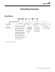
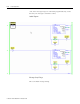
We will look at four methods of reading and writing the system clock.
SLC 500 Controller and Native RS-485 Communications
This example reads and writes the date and time table using the SLC
500 controller Channel 0 serial port and the native RS-485
communications port on the Powermonitor 3000. You must supply an
RS-232 to RS-485 converter such as a 1761-NET-AIC or B&B
Electronics 485SD9TB between the SLC 500 controller and the
Powermonitor 3000.
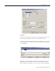
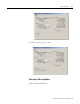
Serial Port Setup
The SLC 500 serial port setup using a 1761-NET-AIC adapter is shown
in Figure . The specific settings will depend on your selection of
RS-485 to RS-232 adapter.