
User Manual, PRIOR to Firmware rev. 3.0 Owner manual


Publication 1404-UM001D-EN-E - October 2004
2-10 Product Description
LED Indicators
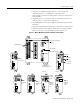
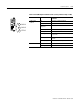
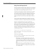
The Powermonitor 3000 is equipped with six, 2-color light emitting
diodes (LEDs) arranged as shown in Figure 2.2. Functions of the LEDs
differ among the various communications configurations.
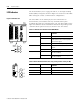
Figure 2.2 LED Indicators
The three LED’s on the left display the same information on
Powermonitor 3000 modules with any communication option
including native RS-485 communications only. The three LED’s on the
right have different labels and different indications depending on the
communications option selected, as shown in the chart below.
Powermonitor 3000
RX
TX
RS-485
MODULE
STATUS
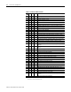
Table 2.2 LED Indicators All Powermonitor 3000 Models
LED LED Color LED State and Communications
Condition
Module Status Off Control power is off or insufficient
Steady Red Major fault; internal self-test has failed. If a
power cycle does not correct the problem,
call customer support
Steady Green Powermonitor 3000 is operating normally
RS-485 RX Off The RS-485 bus is idle; no active data is
present
Flashing Green Active data is present on the RS-485 bus
RS-485 TX Off Powermonitor 3000 is not transmitting data
onto the RS-485 bus
Flashing Green Powermonitor 3000 is transmitting data
onto the RS-485 bus
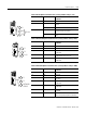
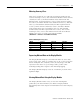
Table 2.3 Native RS-485 Communications only (catalog numbers ending in -000)
LED LED Color LED State and Communications
Condition
F1 Off Not Used
F2 Off Not Used
F3 Off Not Used
Po
wermonitor 3000
wermonitor 3000
F1
F2
F3