
User Manual, PRIOR to Firmware rev. 3.0 Owner manual


Publication 1404-UM001D-EN-E - October 2004
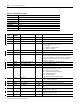
Powermonitor 3000 Data Tables A-25
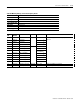
18 30619 Digital board revision 0 to 7 0 = 02A, 1 = 03A, etc.
19 30620 Analog board revision 0 to 7 0 = 02A, 1 = 03A, etc.
20 30621 Reserved 0 Returns 0
21 30622 Reserved 0 Returns 0
22 30623 MM Device ID 0 to 255 Sequentially assigned at time of manufacture. May not be
changed.
23 30624 Master Module type, current 4,5,6,or 8 4 = M4, 5 = M5, 6 = M6, 8 = M8; reflects any upgrades
24 30625 Display module type 0 to 1 0 = No display module connected
1 = 1404-DM connected to master module
25 30626 Option communications type - 00 = No optional communications (native RS-485 only)
81 = DeviceNet V1
82 = ControlNet
84 = Remote I/O
85 = Ethernet Series A
86 = RS-232
88 = DeviceNet V2
89 = IEC870 comm card
90 = Ethernet Series B
26 30627 Accuracy Class 0 to 2 Indicates revenue metering accuracy class as manufactured
(refer to page 3-3).
0 = Class 1
1 = Class 0.5
2 = Class 0.2
Element
No.
Modbus
Address
Element name Range Comment
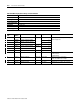
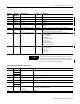
TIP
This is not truly a data table, but a reply to a PCCC
diagnostic status request (used by RSWho to display
text and an icon for the Powermonitor 3000). This
data is not accessible using Modbus.
Table A.17 DF1 PCCC Diagnostic Status Reply
Byte Bits Contents Description
1 0-1 Mode/status Unused
2-3
4-7
2 0-7 Type extender EE
3 0-7 Extended interface type 36h = DF1 half-duplex slave (via native RS485 port or RS-232 port)
65h = Ethernet
4 0-7 Extended processor type 8Ah; 1404 Powermonitor 3000 products
5 0-4 Series/revision Unused
5-7
6-16 All Catalog number
(in ASCII)
Catalog number written into the device at time of production or calibration.
For example ‘1404-M4-05-A-RIO’
17-24 All Product Specific Unused