
User Manual, PRIOR to Firmware rev. 3.0 Owner manual


Publication 1404-UM001D-EN-E - October 2004
A-24 Powermonitor 3000 Data Tables
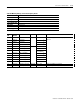
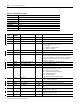
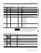
Table A.16 Selftest/Diagnostic Results
CSP File No. N22
Remote I/O BT 36
CIP Assy. Inst. 23
No. of Elements 27
User Configurable No
Data Type Integer
Data Access Read only
PM3000 Type All
Element
No.
Modbus
Address
Element name Range Comment
0 30601 Bulletin number 1404
1 30602 Series 0 to 8 0 = A, 1 = B, etc.
2 30603 Overall status - 0 = OK
3 30604 Data Acquisition status - 0 = OK
bit 0 = overall status; 0 = pass, 1 = fail
bit 1 = reserved
bit 2 = data bus connection failure
bit 3 = address test failure
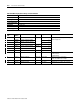
4 30605 Data FLASH status - 0 = OK
5 30606 Real-time clock status - 0 = OK
6 30607 RTC NVRAM status - 0 = OK
Non-zero indicates corruption of non-volatile memory. This
does not cause product to shutdown. The error is cleared on a
reset/power cycle. If this error is detected, date/time, and
energy values are reset.
7 30608 Option communications status - 0 = OK or no optional communications present
8 30609 Display module status - 0 = OK or no DM connected
9 30610 Watchdog status - 0 = OK
10 30611 Code FLASH status - 0 = OK
bit 0 = overall status; 0 = pass, 1 = fail
bit 1 = boot code checksum failure
bit 2 = application code checksum failure
bit 3 = calibration CRC failure
bit 4 = no calibration data
bit 5 = wrong application firmware loaded
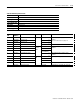
11 30612 RAM status - 0 = OK
bit 0 = read/write test failure
12 30613 Application FRN 0 to 9999 100 indicates V1.00, 103 indicates V1.03, etc.
13 30614 Boot code FRN 0 to 9999 100 indicates V1.00, 101 indicates V1.01, etc.
14 30615 ASIC build # 0 to 9999 Revision number of the ‘code’ which was used to fabricate the
ASIC.
15 30616 Option communications FRN 0 to 9999 100 indicates V1.00, 103 indicates V1.03, etc. 0 = none (catalog
numbers ending in -000, -232)
16 30617 Display module FRN 0 to 9999 104 indicates V 1.04, 105 indicates V1.05, etc.
Returns 0 if no DM connected
17 30618 Reserved 0 Returns 0