
User Manual, PRIOR to Firmware rev. 3.0 Owner manual


Publication 1404-UM001D-EN-E - October 2004
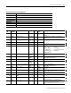
A-16 Powermonitor 3000 Data Tables
RS-232
Element
No.
Modbus
Address
Element name Range Default
Value
Comment
0 40401 Password 0 to 9999 0 Required to change configuration data. Returns -1
1 40402 Hardware port 0 to 1 0 Select active port
0 = RS-232 port
1 = Native RS-485 port
2 40403 Protocol 0 0 0 = DF1 half-duplex slave
3 40404 Delay 0 to 15 2 (10mS) Specifies the delay before responding to an external request.,
useful with slow external devices (such as RF modems)
4 40405 Baud rate 0 to 4 3 0 = 1200 baud
1 = 2400 baud
2 = 4800 baud
3 = 9600 baud
4 = 19200 baud
5 40406 RS-232 address 1 to 254
(1)
Identifies the device on the link. 0 is typically used by the DF1
master. 255 is the broadcast address
6 40407 Data format 0 to 2 0 Parity, number of data bits, number of stop bits
0 = No parity, 8 data bits, 1 stop bit
1 = Even parity, 8 data bits, 1 stop bit
2 = Odd parity, 8 data bits, 1 stop bit
7 40408 Flow Control
(Handshaking)
0 to 1 0 Data flow control for RS-232/RS-485 port.
0 = None
1 = Hardware RTS/CTS
8 40409 RTS On Delay 0 to 9995
ms
0
9 40410
10 40411 Specifies the minimum delay between characters that indicate
s
the end of a message packet. 0 = 3.5 character times.
11 40412 Reserved 0 0 Reserved. Must be 0 on a write, returns 0
12 40413
13 40414
14 40415
15 40416
16 40417
17 40418
18 40419
19 40420
(1) The default address is the same as the ‘Device ID’, which is assigned at the factory and can be found printed on the white label on the side of the master module. The device ID is
incremented for each device.