
User Manual, PRIOR to Firmware rev. 3.0 Owner manual


Publication 1404-UM001D-EN-E - October 2004
Powermonitor 3000 Data Tables A-5
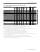
Remote I/O Discrete Data Accepted by Powermonitor (Master Output Data)
Element
No.
Element name Range Comment
1 Relay control 0 or 128 0 (Bit 8 = 0): De-energize
128 (Bit 8 = 1): Energize
Must be enabled by Control source parameter
2 KYZ control
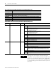
DeviceNet, EtherNet/IP and ControlNet I/O Data Provided by Powermonitor (Scanner Input Data; Instance 1)
Element
No.
Element name Range Comment
0 Relay output status 0 to 3 0 = De-energized & not forced
1 = Energized & not forced
2 = Forced de-energized
3 = Forced energized
1 Solid-state KYZ output status
2 Alarm output word 0 to FFFF Bitfield indicates state of 16 alarm output flags; 0 = released, 1 = asserted
Bit 0 = relay/setpoint output flag 1
Bit 1 = KYZ/setpoint output flag 2
Bit 2 = setpoint output flag 3
…
Bit 15 = setpoint output flag 16
3 Status inputs state 0 to 3 Bit 0 = status input 1; 0 = open, 1 = contact closure detected
Bit 1 = status input 2; 0 = open, 1 = contact closure detected
Bit 2 = demand sync timeout; 1 = the demand delay expired before the next
expected external demand sync. This bit clears when the next external
demand sync occurs. Refer to Table A.6 Advanced Device Configuration
element 23.
Bits 3-15 = unused (always 0)
4 Status input #1 counter 0 to
29,999
Counts to 29,999, rolls over to 0.
5 Status input #2 counter
TIP
Size and content of Instance 1 may vary depending
on user configuration. Refer to User-Configured Data
Table on page 4-53 for more information
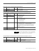
DeviceNet, EtherNet/IP and ControlNet I/O Data Accepted by Powermonitor (Scanner Output Data; Instance 2)
Element
No.
Element name Range Default
Value
Comment
0 Relay output 0 to 1 - 0 (Bit 8 = 0): De-energize
256 (Bit 8 = 1): Energize
Must be enabled by Control source parameter
1 Solid-state KYZ output 0 to 1