
User Manual, PRIOR to Firmware rev. 3.0 Owner manual


Publication 1404-UM001D-EN-E - October 2004
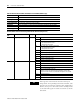
Powermonitor 3000 Data Tables A-3
Transient Analysis Metering Results R • F44 32 54 - 14 • Table A.44
Transient Capture Clear/Read-Back Data Select R/W N45 17 55,56 - 13 • Table A.45
Transient Capture Results R • N46 60 57 -
29 or 59
(11)
• Table A.46
Advanced Metering Configuration R/W N47 19 58,59 - 10 • Table A.47
Harmonic Results; Odd Harmonics 43 to 63 R • F48 45 60 - 14 • Table A.48
Harmonic Results; Even Harmonics 42 to 62 R • F49 46 61 - 14 • Table A.49
Event Log Text R/W • N50 37 62,63 - 23 • Table A.50
Catalog Number and WIN R N51 50 64 32301 29 ••• Table A.51
Network Demand Sync and Time Configuration
(1)
R/W N52 - 65, 66 41901 20 ••• Table A.52
Controller Command
(1)
W N53 - 67 42601 1 ••• Table A.53
Daylight Saving Time Configuration R/W N54 47 68,69 42100 10 ••• Table A.54
Time of Use Register Configuration R/W N55 49 70,71 42200 10 ••• Table A.55
Time of Use Records – Real Energy and Demand R F56 51 72 32300 12 ••• Table A.56
Time of Use Records – Reactive Energy and
Demand
R F57 52 73 32400 12 ••• Table A.57
Time of Use Records – Apparent Energy and
Demand
R F58 53 74 32500 12 ••• Table A.58
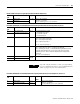
(1) Supported only on 1404-xxxxx-ENT-xx Series B modules.
(2) Data is most commonly read from this table using the Indexed read method. Refer to Indexed reads of large data .
(3) Powermonitor 3000 starts with file 9 to avoid any data-type incompatibility with SLC file numbers 1 through 8, which are of a fixed data type.
(4) This is a reply to a PCCC diagnostic status request, used by RSWho to display text and an icon for the product.
(5) Remote I/O tables and the default DeviceNet input channel are PLC/SLC compatible, but if the user reconfigures the DeviceNet input channel (Instance 1), it may or may
not be PLC/SLC compatible (depending on the number of parameters configured).
(6) Basic device configuration data table size is 8 elements for the M4 and M5, and 9 elements for the M6 and M8.
(7) The size of the Trend log results table is 28 elements for DeviceNet and 44 elements for all other communication protocols.
(8) The size of the Event log results table is 14 elements for M4/M5, 17 elements for M6 and 18 elements for the M8.
(9) The User-configured table results table is populated from the bottom up with the number of parameters the user has configured. The DeviceNet table must contain 14
elements or less to remain PLC/SLC compatible.
(10) Harmonic results; THD, crest factor, and more data table size is 18 elements for the M4 and M5 and 20 elements for the M6 and M8.
(11) The Oscillograph results and Transient capture results tables are 29 elements for DeviceNet and 59 elements for all other communication protocols.
(12) The I/O table is user configurable for DeviceNet and EtherNet/IP only (Instance 1).
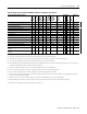
Table A.1 Summary of Powermonitor 3000 Data Tables for all Communications Options
Data Table Name and Description
Data
Access
Indexed
Reads
(2)
File No.
(3)
(DF1, CSP)
Remote I/O
BT Size
Assy
Instance
(CIP, DNet)
Modbus
Starting
Address
No. of
Elements
Applies to
Configur-
able
Refer to
M4, M5
M6
M8