
User Manual, PRIOR to Firmware rev. 3.0 Owner manual


Publication 1404-UM001D-EN-E - October 2004
8-14 Advanced Features
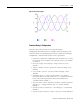
Figure 8.1 Sag and Swell
The pre-defined setpoint configuration for the detection of sag and
swell is based on the IEEE-1159 standard. Although the default
setpoint configuration is applicable as-is for many sag and swell
applications, it may be necessary to alter the setpoint configuration to
adjust the unit’s sensitivity to sags and swells for your particular
application.
Setpoint #19 is setup to detect voltage sag and has the following
configuration data:
• Type = Voltage Sag
• Evaluation condition = Under forward
• High Limit = 90% Nominal System Voltage
• Low Limit = 90% Nominal System Voltage
• Action delay = 0
• Release delay = 0
• Output action = Capture oscillograph
Setpoint #20 is setup to detect voltage swell and has the following
configuration data:
• Type = Voltage Swell
• Evaluation condition = Over forward
• High Limit = 110% Nominal System Voltage
• Low Limit = 110% Nominal System Voltage
• Action delay = 0
• Release delay = 0
• Output action = Capture oscillograph