
User Manual, Firmware rev. 3.0 or LATER Owner's manual


198 Publication 1404-UM001F-EN-P - November 2009
Appendix A Powermonitor 3000 Data Tables
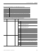
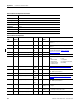
Native Communication Configuration Parameters
CSP File No. N13
Remote I/O BT 11
CIP Assy. Inst. 10 (Write), 11 (Read)
No. of Elements 10
User Configurable No
Data Type Integer
Data Access Read / Write
PM3000 Type All
Native Communication Configuration
Element
No.
Modbus
Address
Element name Range Units Default
Value
Comment
0 40301 Password 0…9999 - 0 Valid password required to change configuration data.
Returns -1
1 40302 Protocol 0…3 - 0 Communication protocol for the native communication port.
0 = DF1 half-duplex slave
1 = Modbus RTU slave
2 = Auto Sense - Selects the protocol based on the incoming
communication packets
3 = DF1 full-duplex
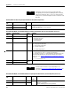
2 40303 Delay 0…15 5 ms 2
(10ms)
Specifies the delay before responding to an external request,
useful with slow external devices (such as RF modems)
3 40304 Baud rate 0…6 - 3 0 = 1.2 Kbps
1 = 2.4 Kbps
2 = 4.8 Kbps
3 = 9.6 Kbps
4 = 19.2 Kbps
5 = 38.4 Kbps
6 = 57.6 Kbps
4 40305 Device address 1…247 -
(1)
Identifies the device on a multi-drop network. DF1 master
typically uses 0. The broadcast address is 255
5 40306 Data format 0…2 - 0 Parity, number of data bits, number of stop bits
0 = No parity, 8 data bits, 1 stop bit
1 = Odd parity, 8 data bits, 1 stop bit
2 = Even parity, 8 data bits, 1 stop bit
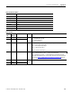
6 40307 Inter-Character
Timeout
0…6553 ms 0 Specifies the minimum delay between characters that
indicates the end of a message packet.
0 = 3.5 character times
7 40308 Error checking 0…1 - 0 0 = CRC
1 = BCC
8 40309 Reserved 0 - 0 Returns 0
9 40310
(1)
The default address is the Device ID, which is factory assigned and is found on the label on the side of the master module. The device ID is incremented for each device.