
User Manual, Firmware rev. 3.0 or LATER Owner's manual


Publication 1404-UM001F-EN-P - November 2009 193
Powermonitor 3000 Data Tables Appendix A
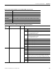
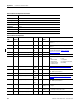
Discrete Data Parameters
CSP File No. N9
Remote I/O BT 10
CIP Assy. Inst. 3
No. of Elements 6
User Configurable No
Data Type Integer
Data Access Read Only
PM3000 Type All
Discrete Data
Element
No.
Modbus
Address
Element name Range Comment
0 30001 Relay output status 0…3 0 = De-energized and not forced
1 = Energized and not forced
2 = Force De-energized
3 = Force Energized
1 30002 Solid-state KYZ output
status
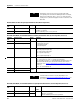
2 30003 Alarm output word 0…FFFF Bitfield indicating state of the 16 alarm output flags; 0 = released, 1 = asserted.
Bit 0 = relay/setpoint output flag 1
Bit 1 = KYZ/setpoint output flag 2
Bit 2 = setpoint output flag 3
…
Bit 15 = setpoint output flag 16
3 30004 Status inputs state 0…7 Bit 0 = status input #1; 0 = open, 1 = contact closure detected
Bit 1 = status input #2; 0 = open, 1 = contact closure detected
Bit 2 = demand sync timeout; 1 = the demand delay expired before the next
expected external demand sync. This bit clears when the next external demand
sync occurs. Refer to
Advanced Device Configuration Parameters element 23.
Bits 3…15 = unused (always 0)
4 30005 Status input #1 counter 0…
29,999
Counts to 29,999, rolls over to 0
5 30006 Status input #2 counter