Bulletin 1404 Powermonitor 3000 Catalog Numbers 1404-M4, 1404-M5, 1404-M6, 1404-M8 User Manual
Important User Information Solid state equipment has operational characteristics differing from those of electromechanical equipment. Safety Guidelines for the Application, Installation and Maintenance of Solid State Controls (publication SGI-1.1 available from your local Rockwell Automation sales office or online at http://www.rockwellautomation.com/literature/) describes some important differences between solid state equipment and hard-wired electromechanical devices.
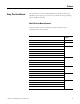
Summary of Changes Introduction This release of this document contains new and updated information. To find new and updated information, look for change bars, as shown next to this paragraph. Updated Information The document contains these changes Topic Page Added information about single-instance parameters 19 Single instance parameter for DeviceNet 77 Added Single Element Writes to the primary 80 methods to communicate with a power monitor 3Publication XXXX-X.X.
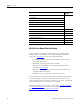
Summary of Changes Topic Page Added Single Password Write data tables 266 Added Single Parameter Read data tables 267 Added sample applications: Appendix C • Read and write power monitor tables by using an SLC 500 controller and a 1747-SCNR ControlNet scanner. • Read and write power monitor tables by using a MicroLogix controller over EtherNet/IP and Modbus RTU communication networks. • Read and write power monitor tables by using a Component HMI over an EtherNet/IP communication network.
Table of Contents Preface Using This User Manual. . . . . . . . . . . . . . . . . . . . . . . . . . . . . 7 Additional Resources. . . . . . . . . . . . . . . . . . . . . . . . . . . . . . . 9 Terms and Conventions. . . . . . . . . . . . . . . . . . . . . . . . . . . . . 9 Chapter 1 Safety Safety Considerations . . . . . . . . . . . . . . . . . . . . . . . . . . . . . 11 Other Precautions . . . . . . . . . . . . . . . . . . . . . . . . . . . . . . . . 12 Chapter 2 Product Description Master Module . . .
Table of Contents Chapter 8 Advanced Features Oscillography . . . . . . . . . . . . . . . . . . . . . . Harmonic Analysis . . . . . . . . . . . . . . . . . . Sag and Swell . . . . . . . . . . . . . . . . . . . . . . Load Factor. . . . . . . . . . . . . . . . . . . . . . . . Transient Detection, Metering and Capture. . . . . . . . . . . . . . . . . . . . . . . . . . . . . . . . . . . . . . . . . . . . . . . . . . . . . . . . . . . . .
Preface Using This User Manual You should have a basic understanding of electrical circuitry and familiarity with relay logic. If you do not, obtain the proper training before using this product. What This User Manual Contains Review the table below to familiarize yourself with the topics contained in this User Manual.
Preface Preface For information about Refer to Chapter Advanced Features 8 Oscillography Harmonic Analysis Sag and Swell Load Factor Transient Detection, Metering and Capture Powermonitor 3000 Data Tables A Catalog Number Explanation B Sample Applications C Technical Specifications D Frequently Asked Questions E Glossary Glossary Index Index What This User Manual Does Not Contain Topics related to installation and wiring are not covered in this manual.
Preface Additional Resources Preface Refer to these power and energy management documents for more information. For this information Refer to Publication Powermonitor 3000 Installation Instructions (all communication options) 1404-IN007 Bulletin 1404 Powermonitor 3000 Display Module Installation Instructions 1404-IN005 Bulletin 1404 Series B Ethernet Communication Release Note 1404-RN008 You can view or download publications at http://www.rockwellautomation.com/literature.
Preface 10 Preface Abbreviation Term RAM Random Access Memory RTOS Real Time Operating System R I/O Remote Input/Output PCCC Rockwell Automation’s proprietary Programmable Controller Communication Commands protocol RMS Root–mean–square SNTP Simple Network Time Protocol SPDT Single Pole Double Throw SLC Small Logic Controller UL Underwriters Laboratories VA Voltampere VAR Voltampere Reactive Publication 1404-UM001F-EN-P - November 2009
Chapter 1 Safety Safety Considerations Before installing and using this product, please read and understand the following precautions. ATTENTION ATTENTION IMPORTANT IMPORTANT 11Publication 1404-UM001F-EN-P - November 2009 Only qualified personnel, following accepted safety procedures, should install, wire and service the Powermonitor 3000 unit and its associated components. Before beginning any work, disconnect all sources of power and verify that they are de-energized and locked out.
Chapter 1 Safety Other Precautions ATTENTION Electrostatic discharge can damage integrated circuits or semiconductors. Follow these guidelines when you handle the module. • Touch a grounded object to discharge static potential. • Wear an approved wrist strap-grounding device. • Do not open the module or attempt to service internal components. • Use a static safe workstation, if available. • Keep the module in its static shield bag when not in use.
Chapter 2 Product Description The Bulletin 1404 Powermonitor 3000 unit is designed and developed to meet the needs of both producers of and users of electric power. A power monitor system consists of: • a master module that provides metering, data logging, native RS-485 communication, and other advanced features depending on the model. • an optional display module for configuration, entering commands, and displaying data.
Chapter 2 Product Description Master Module The master module contains the main microprocessor-based monitoring functions, including terminations for power system connections, status inputs, control outputs, a native RS-485 communication port, and a port for the display module. Configuration Although the power monitor ships from the factory with default settings, you need to configure it for your particular requirements. You may configure the power monitor by using the optional display module.
Product Description Chapter 2 You may integrate a power monitor into a programmable controller based control and monitoring system by using your choice of the native or optional communication methods. Display Module The Bulletin 1404 display module is an optional user interface device. The display module provides the most economical and simplest method for setting up and configuring the master module for operation.
Chapter 2 Product Description Performance Features The power monitor is available in four basic models, designated M4, M5, M6, and M8. Each model offers specific functionality as indicated in this table. The M5 model offers M4 functionality and can be field-upgraded to an M6 or M8 model for an additional charge.
Product Description Communication Options Chapter 2 In addition to the native RS-485 communication port, several factory-installed communication options are also available. These options make it possible for a user to select Powermonitor 3000 units to provide power and energy information into a variety of existing or new control systems and communication networks. Each communication option supports bi-directional data transfer with external devices or applications.
Chapter 2 Product Description RS-232 Optional Communication A catalog number ending in -232 specifies a power monitor with one RS-232 communication port in addition to the native RS-485 communication port. You select which of the two ports is active, as the two ports may not be used concurrently. The RS-232 port supports the same performance features as the RS-485 port, with the following exceptions: • • • • RS-232 cable length 15.
Product Description Chapter 2 DeviceNet Optional Communication A catalog number ending in -DNT specifies a power monitor with a DeviceNet port in addition to the native RS-485 port. The DeviceNet option permits concurrent use of both communication ports.
Chapter 2 Product Description • Compatible with commercially available network bridges, routers, hubs and switches • Fully software configurable • Supports RSLinx software • Supports Allen-Bradley Client Server Protocol (CSP) • Supports EtherNet/IP (CIP) protocol • Configurable I/O channel assembly instance: six parameters default, twenty-three maximum • Configurable explicit assembly instance: seventeen parameters default, twenty-three parameters maximum • Explicit assembly instances for access to all da
Product Description Chapter 2 • Supports up to 64 concurrent Class 1 connections to instance 1 and one Class 1 connection to Instance 2.
Chapter 2 Product Description Status Indicators The power monitor is equipped with six, two-color status indicators arranged as shown. Functions of the indicators differ among the various communication configurations. Status Indicators Powermonitor 3000 MODULE STATUS RX RS-485 TX The three indicators on the left, display the same information on Powermonitor 3000 units with any communication option including native RS-485 communication only.
Product Description Chapter 2 Native RS-485 Communication Only (catalog numbers ending in -000) Powermonitor 3000 F1 F2 F3 Status Indicator Indicator Color Indicator State and Communication Condition F1 Off Not Used F2 Off Not Used F3 Off Not Used RS-232 Optional Communication (catalog numbers ending in -232) Powermonitor 3000 Status Indicator Indicator Color Indicator State and Communication Condition F1 Off Not Used RS-232 RX Off The RS-232 bus is idle; no active data is present
Chapter 2 Product Description DeviceNet Optional Communication (catalog numbers ending in -DNT) Status Indicator Indicator Color Indicator State and Communication Condition F1 Off Not Used F2 Off Not Used Network Status Off Power is off or the power monitor is not online Flashing Green Network status is OK, no connections established Steady Green Network status is OK, connections established Flashing Red Recoverable communication failure; port is restarting Steady Red Non-recoverable co
Product Description Chapter 2 ControlNet Optional Communication (catalog numbers ending in -CNT) Status Indicator Indicator Color Indicator State and Communication Condition CHAN A and CHAN B Off No power or Channel disabled Steady Red Faulted unit Alternating red/green Self-test Alternating red/off Incorrect node configuration Steady green Normal operation Flashing green/off Temporary errors or node is not configured to go online Flashing red/off Media fault or no other nodes present on
Chapter 2 26 Product Description Publication 1404-UM001F-EN-P - November 2009
Chapter 3 Powermonitor 3000 Unit Operations The Powermonitor 3000 unit is a microprocessor-based electrical power- and energy-measuring device. It connects to your three-phase or single-phase ac power system directly or through instrument transformers (PTs and CTs). It converts instantaneous voltage and current values to digital values, and uses the resulting digital values in calculations of things such as voltage, current, power, and energy.
Chapter 3 Powermonitor 3000 Unit Operations Summary of Measurements M4 M6 M8 DM(1) M5 • • • • • • • • • • • • • • • • • • • • • • • • • • • • • • • • • • • • • • • • • • • • • • • • • • • • • • • • • • • • • • • • • • • • • • • • • • • • • • • • • • • • • • • • • • • • • • • • • • • • • • • • • • • • • • • • • • • • • • • • • • • • • • • • • • • (1) 28 Measurement Current, per phase and neutral Average current Positive sequence current Negative sequence current Percent current unbalanc
Powermonitor 3000 Unit Operations Chapter 3 Metering Accuracy Class In the Selftest/Diagnostic Results table, element 26 is a read-only parameter that indicates the revenue metering accuracy class of the master module. If this element contains the value 0, the master module meets ANSI C12.16 and EN61036 Class 1 requirements for accuracy. If this element contains the value 1, the master module meets ANSI C12.20 Class 0.5, EN60687 Class 0.5, and Canadian standard CAN3-C17-M84 requirements for accuracy.
Chapter 3 Powermonitor 3000 Unit Operations Voltage, Current, and Frequency Results Line-to-line voltage results (L1-L2, L2-L3, and L3-L1) are calculated for all wiring modes. Line-to-neutral voltage results (L1-N, L2-N, and L3-N) are calculated in wye and single-phase wiring modes only. In delta wiring modes, line-to-neutral voltages return a zero value. Average line-to-line (Avg. L-L) and line-to-neutral (Avg.
Powermonitor 3000 Unit Operations Chapter 3 • Frequency Averaging – like the RMS result averaging, the default setting provides for a smoother response by averaging the frequency of each of the last eight cycles. You may select no averaging to return the frequency of only the last cycle Refer to Advanced Device Configuration on page 50 for more information.
Chapter 3 Powermonitor 3000 Unit Operations Voltage, Current, and Frequency Metering Parameter Phase 1 L-N Voltage Phase 2 L-N Voltage Phase 3 L-N Voltage 3-Phase Average L-N Voltage Phase 1 L-L Voltage Phase 2 L-L Voltage Phase 3 L-L Voltage 3-Phase L-L Voltage Phase 1 Current Phase 2 Current Phase 3 Current 3-Phase Average Current Phase 4 (Neutral) Current Frequency Phase Rotation Voltage Positive Sequence Voltage Negative Sequence Current Positive Sequence Current Negative Sequence Voltage Unbalance C
Powermonitor 3000 Unit Operations Chapter 3 Power Factor Results The power monitor calculates true, displacement and distortion power factor, each on a per-phase and total three-phase basis. True power factor is the ratio between the total true power and total apparent power (in percent), and takes into account the effect of phase shift between the voltage and current as well as any harmonics present.
Chapter 3 Powermonitor 3000 Unit Operations Power and Power Factor Results Parameter Description Range Units Phase 1 True Power Factor The ratio between the power and apparent power for an individual phase or all three phases; signed to show lead (+) or lag (-). -100…100 Percent The ratio between the magnitude of the fundamental and the sum of the magnitudes for all of the current harmonics for an individual phase or all three phases.
Powermonitor 3000 Unit Operations Chapter 3 Configurable Energy Counter Rollover You may configure the number of digits at which energy values roll over to zero. The parameter range is 4…15 digits. Configure this setting in Advanced Device Configuration by using the display module or by writing to the Advanced Device Configuration table on page 196. This setting lets you optimize the energy counter rollover for use with applications that support a limited number of significant digits.
Chapter 3 Powermonitor 3000 Unit Operations The utility may provide a pulse that indicates the end of each demand interval. The utility updates the demand value at the end of each interval and maintains the highest value obtained during any interval. This method is known as thermal demand. You may set up a power monitor to determine its demand interval from the utility pulse.
Powermonitor 3000 Unit Operations Chapter 3 Instantaneous The power monitor computes instantaneous demand by substituting the elapsed interval duration for the total interval duration (T) in the demand equation. It is therefore identical to the standard computation except it integrates the power only over the elapsed interval duration and calculates the average value over the elapsed duration. The modified equation thus becomes.
Chapter 3 Powermonitor 3000 Unit Operations Energy and Demand Results Parameter Kilo-Watt Hours Forward Kilo-Watt Hours Reverse Kilo-Watt Hours Net Kilo-VAR Hours Forward Kilo-VAR Hours Reverse Kilo-VAR Hours Net Kilo-VA Hours Net Description The total real power consumed The total real power produced The sum of forward and reverse power The total reactive power consumed The total reactive power produced The sum of forward and reverse reactive power The total apparent power consumed Range 0…1.
Powermonitor 3000 Unit Operations Chapter 3 Key Functions The display module has four keys located on its front bezel: an Escape key, Up Arrow key, Down Arrow key, and an Enter key. These keys differ slightly in how they function in each mode. See Menu/Parameter Structure on page 40 for a description of their functionality.
Chapter 3 Powermonitor 3000 Unit Operations Menu/Parameter Structure Chart Key Default Screen Level 1 Default Screen? Level 2 Next Item (Within Current Level) Level 1 Level 3 Display Program Level 4 Previous Item (Within Current Level) Select Program Password? Level 2 Display Metering Display Harmonics Display Logs Level 3 Metering V,I,F(2) Metering Power(3) Metering Σ Power(4) Harmonics L1,L2,L3,N(1) Event Log Volts L1-N Volts L2-N Volts L3-N Volts 3Ph Ave L-N Amps L1 Amps L2 Amps L3 Amps
Powermonitor 3000 Unit Operations Chapter 3 Configuration Menu Level 3 Basic Wiring Mode PT Primary PT Secondary CT Primary CT Secondary I4 Primary I4 Secondary Nominal Sys Voltage (7) Level 2 Native Comm.
Chapter 3 Powermonitor 3000 Unit Operations Displaying Information The display screen consists of two rows of five alpha-numeric LED digits. At the right of this screen is a column of phase indicators: L1, L2, L3 and N. These indicators show which phase (or phases) is referred to by the information being displayed on the 2x5 screen. The phase indicators also indicate program mode by flashing.
Powermonitor 3000 Unit Operations Chapter 3 Scrolling When messages are too large to fit on the display, a scrolling mechanism is employed. The message scrolls horizontally. The default scroll rate was chosen to give you enough time to see the message but not take too much time to show the entire message. You may select from two different scroll rates by using the Advanced Configuration Menu on the display module.
Chapter 3 Powermonitor 3000 Unit Operations 3. Change the value of the parameter by pressing the Up Arrow and Down Arrow keys until the desired parameter value is displayed. Notice the phase indicators on the right-hand side remain solid and the parameter being modified is still flashing. 4. After the desired parameter value is displayed, press the Enter key to write the new value to the master module and set the display module back to Program mode.
Powermonitor 3000 Unit Operations ATTENTION Chapter 3 The relay and KYZ outputs may be connected to field devices. Before issuing a command to force an output, ensure that any devices connected to outputs cannot operate in an unsafe or undesired manner. Failure to follow these instructions may result in personal injury or death, property damage, or economic loss. 1. Using the four display module keys, move into Program mode and display the command to be issued.
Chapter 3 Powermonitor 3000 Unit Operations 3. Choose the option of the command by pressing the Up Arrow and Down Arrow keys until the desired option is displayed. Notice the phase indicators on the right-hand side remain solid and the command option being selected is still flashing. Command Option Powermonitor 3000 LAY-1 Energ L1 L2 L3 N 4. After the desired command option is displayed, press the Enter key to execute the command.
Powermonitor 3000 Unit Operations Chapter 3 Commands Parameter Description Range Force Relay Forces relay to a known state in which the relay remains at that state until the force is removed. De-energize Energize No Force Force KYZ Forces KYZ to a known state in which the relay remains at that state until the force is removed. De-energize Energize No Force Clear Min/Max Log Resets the Min/Max log with the current real time metering information.
Chapter 3 Powermonitor 3000 Unit Operations Refer to the Device Configurations Summary table on page 50 for a summary of basic and advanced device configuration settings. You may use a copy of this table to record your configuration settings. Basic Device Configuration The basic unit configuration sets the wiring mode, PT ratios and CT ratios to match your power system. Every power monitor requires basic configuration.
Powermonitor 3000 Unit Operations Chapter 3 PT and CT Ratios You may directly connect the voltage inputs of the power monitor to power systems rated at 600V line-to-line or less. Above 600V, you need potential transformers (PTs) to step down the power system voltage to one that is measurable. Most commercially available PTs have a secondary rated voltage of 120V (150V full-scale). Nearly every power monitor installation requires CTs to step down the power system current to a value of 5 A full-scale.
Chapter 3 Powermonitor 3000 Unit Operations Advanced Device Configuration A number of parameters are grouped into Advanced Configuration, including the Password, demand and projected demand setup, relay and KYZ pulse operation setup, metering accuracy options, date/time and display module scrolling rate. To perform advanced configuration by using the display module, navigate through these menus: PROG. > PASS? > CONFIGURATION > ADVANCED.
Powermonitor 3000 Unit Operations Chapter 3 Device Configurations Summary Parameter New Password Demand Period Length Number of Demand Periods Forced Demand Delay Predicted Demand Type Advanced Configuration KYZ Control Source KYZ Pulse Output Scale KYZ Pulse Output Width Relay Control Source Relay Pulse Output Scale Relay Pulse Output Width RMS Resolution RMS Averaging Frequency Averaging Date Format Date: Year Date: Month Date: Day Time: Hour Time: Minutes Time: Seconds Default relay state on comms l
Chapter 3 Powermonitor 3000 Unit Operations Demand Setup You may configure the demand period length, the number of demand periods to average for demand calculation, the forced demand delay and the type of calculation used for projected demand. Demand Period Length sets the length in minutes (1…99) of the demand period used for demand and projected demand calculation. Range –99…99, default 15.
Powermonitor 3000 Unit Operations Chapter 3 • sends out a demand sync broadcast when configured as a Master (Ethernet units). • starts the projected demand calculations from the beginning again. Entering a value of 0 disables this function. For more information about this feature read the section Network Demand / Time Configuration on page 55. Projected Demand Type specifies the type of calculation used for projected demand.
Chapter 3 Powermonitor 3000 Unit Operations Metering Options Configuration parameters RMS Result Averaging, RMS Resolution and Frequency Averaging allow you to make choices to fit the power monitor more closely to your application needs. The default settings are to average 8 RMS and frequency calculations, providing a smoother result, and to sample at a high rate, providing greater accuracy where significant harmonics are present.
Powermonitor 3000 Unit Operations Chapter 3 Date and Time You may use these parameters to set the power monitor’s internal clock and calendar and configure the display format as MM/DD/YYYY (default) or DD/MM/YYYY. The power monitor uses its internal clock time-stamp entries in logs, oscillograms and transient captures. Display Mode Scroll Speed This parameter controls how fast text that doesn’t fit in the window is scrolled on the display module. Default is fast scrolling.
Chapter 3 Powermonitor 3000 Unit Operations Ethernet units also support synchronization of their internal clocks from up to three SNTP servers, at a configurable synchronization interval. Since SNTP servers operate in UTC (Universal Coordinated Time), a time zone for the power monitor must also be configured for the correct time to be set. The time zone is configured as an offset in hours from UTC (formerly known as GMT).
Powermonitor 3000 Unit Operations Chapter 3 SNTP Address 2 The IP address of the primary SNTP server, accessed as the 1st…4th octet. SNTP Address 3 The IP address of a third SNTP server, accessed as the 1st…4th octet.
Chapter 3 Powermonitor 3000 Unit Operations DST (Daylight Saving Time) Configuration The power monitor may be configured to automatically adjust its internal clock for daylight saving time. You may configure the daylight saving time function by using the display module or via communication by writing to the Daylight Saving Time Configuration table. DST Enable Enables the daylight saving time function.
Powermonitor 3000 Unit Operations Chapter 3 DST is disabled by default. When enabled, the default start time is 2:00 a.m. on the second Sunday in March, and the default end time is 2:00 a.m. on the first Sunday in November. This corresponds to US Daylight Saving Time beginning in 2007.
Chapter 3 Powermonitor 3000 Unit Operations Metering Update Rate The metering update rate is a measure of how often the power monitor calculates new metering results. The metering update rate is not significant in most applications, but can be important in some control applications. The metering update rate affects how quickly a setpoint can respond to an electrical event and affects how often new metering results are available for communication.
Powermonitor 3000 Unit Operations Chapter 3 Out-of-the-box metering update rates are based on factory-default configuration data and are listed in the Meter Update Rate with Factory Default Configuration table for all power monitor models and communication options. Factory default settings for configuration parameters can be found in Appendix A.
Chapter 3 62 Powermonitor 3000 Unit Operations Publication 1404-UM001F-EN-P - November 2009
Chapter 4 Communication The communication features of the Powermonitor 3000 unit make it uniquely suited to integrate electric power usage information into your industrial control and information systems. Every power monitor is equipped with a native RS-485 communication port, and you can select optional communication that facilitate seamless integration with a variety of industrial networks.
Chapter 4 Communication If you choose to configure communication parameters by using communication, please refer to the Native Communication Configuration table and the Optional Communication Configuration Parameters table in Appendix A. Native RS-485 Communication Your Powermonitor 3000 unit is set up to communicate via its native RS-485 port when you first power it up, except for units with an optional RS-232 communication port.
Communication Chapter 4 Range Default User Setting DF1 Full-duplex DF1 Half-duplex Slave Modbus RTU Slave Auto-Sense Auto-Sense Native Communication Configuration Summary Parameter Description Protocol Delay Time between receiving a request and transmitting a response 0…75 ms 10 ms Communication Rate RS-485 port communication bit rate 1.2 Kbps 2.4 Kbps 4.8 Kbps 9.6 Kbps 19.2 Kbps 38.4 Kbps 57.
Chapter 4 Communication The RS-232 communication standard supports point-to-point communication between TWO stations or nodes, with a maximum cable length of 15.24 m (50.0 ft). You may not use the optional RS-232 port and the native RS-485 port at the same time.
Communication Chapter 4 Auto Configure Instructions for DF1 Full-duplex Verify that the latest EDS files have been installed for firmware revision 3. Follow these steps to configure DF1 full-duplex. 1. Select the serial DF1 driver from the selection menu and click Add New. 2. Select the default driver name or provide your own. 3. When presented with the configuration screen you may use the auto configure feature or enter your own configuration.
Chapter 4 Communication To use the auto configure you must first select the device as SLC-CH0/Micro/PanelView. 4. Click Auto Configure to start the process. The configuration returns with the following message. This message can be disregarded. Recognition of the device is provided after exiting the auto configuration routine. 5. Click OK and disregard this message.
Communication Chapter 4 The successful configuration of DF1 full-duplex should look like this. 6. Return to the main browsing window of the RSLinx application and browse to the DF1 Driver for the Powermonitor 3000 unit. The result is an established communication link between the application and the powermonitor.
Chapter 4 Communication Optional Remote I/O Communication Powermonitor 3000 units with a catalog number ending in -RIO are equipped with an optional remote I/O port in addition to the native port. This dual-port option allows the use of both ports simultaneously. The port emulates a logical quarter-rack of I/O. You must configure the rack address, group number, communication rate and last rack status.
Communication Chapter 4 Optional DeviceNet Communication Powermonitor 3000 units with a catalog number ending in -DNT are equipped with an optional DeviceNet communication port in addition to the native port. Both may operate at the same time. You must configure the DeviceNet communication parameters before you connect the power monitor to a DeviceNet network. The DeviceNet configuration parameters include node address (or MAC ID), baud rate, and bus-off interrupt response.
Chapter 4 Communication TIP Some legacy power monitor units with optional DeviceNet communication do no support remotely settable node addressing, AutoBaud, or Program Baud. You can check whether your power monitor supports these functions by viewing the Optional Communication Card status by using your display module. Communication type 81 does not support these functions, type 88 does. You may also view this status item by a read of assembly instance 23, element 25.
Communication Chapter 4 Configure the Powermonitor 3000 Unit by using RSNetworx for DeviceNet Software TIP The DeviceNet network is an open-standard, multi-vendor communication network. Although other vendors offer DeviceNet configuration tools, all examples in this manual will depict the use of Rockwell Software RSNetWorx for DeviceNet software. 1. Launch RSNetWorx for DeviceNet software. At this point, the DeviceNet scanner module does not know what device to scan. 2.
Chapter 4 Communication The available networks are displayed. 3. Click the network. The network devices are displayed.
Communication Chapter 4 4. Read the scanner’s configuration. Right-click on the DeviceNet scanner icon and upload the scanner’s present configuration. 5. Edit the Scanner List. The DeviceNet scanner needs to know how the information is coming from the Powermonitor 3000 unit. Select the Scan List tab and move the power monitor into the Scanlist set. 6. Edit the Data Table Map.
Chapter 4 Communication The DeviceNet scanner needs to know which bytes are scanned from the power monitor. Select the Input tab. This lets you determine where the information is stored inside the scanner module. When finished configuring, click Apply. 7. Click Download to Scanner. All of the configuration data must be downloaded to the scanner module. 8. Download All Records, and allow the scanner to reset.
Communication Chapter 4 Afterwards, the DeviceNet scanner displays an 80, followed by a 00 when everything is configured properly. TIP Powermonitor 3000 units Input parameters are Instance 1 and output parameters are Instance 2. DeviceNet Single Instance Parameters Powermonitor 3000 units with DeviceNet communication and master module firmware revision 4.x and later include 23 single-instance parameters.
Chapter 4 Communication Optional Ethernet Communication Powermonitor 3000 units with a catalog number ending in -ENT are equipped with an optional Ethernet 10/100BaseT communication port and a native RS-485 port in a dual-port configuration that allows simultaneous operation of the ports. You must configure the communication parameters before you connect your power monitor to an Ethernet network. See your network administrator for assistance in setting the communication options.
Communication Chapter 4 In this example, the NetID is 192.1.1.0 and the HostID is 0.0.0.207. The relationship between NetID and HostID depends on the IP address class, the discussion of which is beyond the scope of this document (the example uses a Class C IP address). Devices on the same subnet can communicate directly; devices on different subnets may communication with each other only through a gateway or router.
Chapter 4 Communication Data Messaging Overview Through communication, the power monitor becomes an effective source of power and energy data to enterprise information and automation systems. This section of the manual provides an overview of data messaging with the power monitor. Following the overview, discussions will focus on the details of messaging using specific communication types (for example, serial, remote I/O, DeviceNet, and Ethernet). The power monitor is a read/write data server.
Communication Chapter 4 Powermonitor 3000 Unit Data Table Attributes Powermonitor 3000 unit data table attributes include their addressing, data access, number of elements, data type, and user-configurability. Address - Data tables are addressed in a number of ways, depending on the type of communication and the protocol being used.
Chapter 4 Communication Let’s look at the Date and Time table as an example. • • • • • • • • CSP file number: N11 Remote I/O BT length: 12 CIP assembly instance: 6 (Write) or 7 (Read) Data table name: Date and Time Data access: Read/write Number of elements: 8 Data type: Integer User-configurable: No The power monitor data tables are listed in Appendix A. The table on page 188 shows a summary of all the data tables.
Communication Chapter 4 Timestamp format. The power monitor expresses timestamps in an array of four data table elements: Year, Month/Day, Hour/Minute, Second/ Hundredth of a second Each timestamp parameter (except the Year) is a combination of its first and second element. For instance, the Month is the parameter value divided by 100 and the remainder is the Day. Example: 1230 = December 30th. The timestamp data type may be integer or floating-point and depends on the data table.
Chapter 4 Communication A valid write to a data table must meet the following general criteria: • The length of the source data array must equal the data table length. Note that the same data table may have a different length in various power monitor models. • The entire data table must be written in one pass. • The first element in the source data array must generally contain the correct password (or a value of -1 for read-back data selection).
Communication Chapter 4 Data Table Write Flow Diagram Programmable Controller (Data Client) Powermonitor 3000 (Data Server) Allen-Bradley Element 0 1 2 3 4 5 ... n Element 0 1 2 3 4 5 ...
Chapter 4 Communication Single Element Data Writes A single element write to a data table must meet the following general criteria: • A valid password is written to Table 60, element 0 to enable single element writes. • The source and destination data type and length must match, for example, floating point or integer, 4 bytes or 2 bytes. • The source data element must be within the legal range listed in the data table specification. • Reserved elements may not be written.
Communication Chapter 4 Simple Reads of Data Tables The following considerations apply to simple power monitor data table reads: • An entire data table or a contiguous portion (down to a single element) may be read, except for remote I/O and DeviceNet optional communication which require that an entire table be read • The target data location should match the size and data type of the data requested You may use simple reads to obtain basic metering data, configuration data, date and time, and the contents
Chapter 4 Communication Indexed Reads of Large Data Structures Large data structures that require indexed reads are most often read into a computer-based application that performs further processing of the data. The power monitor parses logs, oscillograms, harmonic analysis results, setpoint status results, and other large data structures into individual records to be read by the client and reassembled into the original data structure. You may select one of two modes for indexed table reads.
Communication Chapter 4 Indexed Data Read, Manual Mode Flow Diagram Refer to Chapter 5, Setpoint Programming and Operation; Chapter 7, Data Logging; and Chapter 8, Advanced Features for details of indexed mode data reads for each of these functions.
Chapter 4 Communication I/O Type Communication Powermonitor 3000 units with optional remote I/O, EtherNet/IP, ControlNet, and DeviceNet communication provide I/O type (implicit) messaging. Remote I/O units emulate a logical quarter rack on the I/O channel. The corresponding, two-word output and input image table elements are automatically scanned by the I/O scanner, and the data points they contain are available for use in the logic program of the controller associated with the I/O scanner.
Communication Chapter 4 Serial Communication Options The native RS-485 and optional RS-232 communication ports provide basic serial asynchronous communication capabilities. The RS-485 communication standard supports multi-drop communication between a master station and up to 31 slaves on a single network up to 1219 m (4000 ft) long. For satisfactory communication performance, however, we recommend connecting no more than 8…12 power monitors to an RS-485 multi-drop network.
Chapter 4 Communication IMPORTANT Because the floating-point word order in the ControlLogix controller is reversed from that in the power monitor, your ladder logic needs to reverse the word order so the data may be interpreted correctly. The swap byte (SWPB) instruction performs this function. Because of the DF1 protocol’s inherent handshaking, the completion of each message may be used to activate the next message, without any additional programmed delay.
Communication Chapter 4 The power monitor does not initiate Modbus commands but responds to commands sent by the Modbus master. The following Modbus function codes are supported: • 03 Read Holding Registers • 04 Read Input Registers • 16 Write Multiple Holding Registers • 08 Diagnostics – 00 Echo Command Data – 02 Return Diagnostic Counters – 10 Clear Diagnostic Counters • 06 Write Single Holding Register Function 06, 16 and the sub function 10 of function 08 support Broadcast packets.
Chapter 4 Communication The data table number of error request and element offset of error request in the Write Error Status table is updated with the first Modbus address of the table and element offset that the incoming request packet attempts to write to. Modbus Error Codes Error Code Description Meaning Response Exception Code 0 No error. None 1 Function Code The function does not support Broadcast. cannot Broadcast.
Communication Chapter 4 For function code 16, if the data length is larger or less than the element number of the data table accessed, error code 4 occurs. It means the data length for function code 16 should be strictly the same as the size of the accessed data table. If the data written to the power monitor by using function code 16 is outside of the legal range as shown in Appendix A, error code 5 occurs.
Chapter 4 Communication DeviceNet Communication Option The Powermonitor 3000 units with optional DeviceNet communication operate as a slave device on a DeviceNet network. It serves data to a DeviceNet master station such as a PLC-5 or SLC 500 DeviceNet scanner module, a ControlLogix DeviceNet bridge module, a PanelView operator terminal and RSLinx direct and pass-thru DeviceNet drivers.
Communication Chapter 4 Polled I/O messaging can automatically provide fresh data at update rates as fast as 100 ms. The power monitor supports both Every Scan and Background polled messaging. You select the poll type and polling rate by using RSNetworx for DeviceNet software. • Every Scan: Polls the power monitor once per scan. Set the Interscan Delay to at least 100 ms. An Interscan Delay of less than 100 ms slows the power monitor’s delivery of metering information.
Chapter 4 Communication Please contact Rockwell Automation technical support if you find that the default settings do not result in adequate network performance. Explicit Messaging Use explicit messaging to read and write all data tables other than the I/O messaging table. The specific details of explicit messaging depend upon the master device that initiates the message. The example in this section uses an Allen-Bradley SLC 500 controller and DeviceNet Scanner (1747-SDN) as the master.
Communication Chapter 4 Word 0 contains a transmit identifier (TXID) and command byte. Assign each explicit message a unique TXID in the range of 0…255 decimal (0 to FF hex). The TXID is used to identify the response to this message request. These are valid command codes: • 1 hex = Execute transaction block. Use this command first to start the explicit message. • 4 hex = Delete transaction from response queue.
Chapter 4 Communication Once the message is assembled, your ladder program transfers the integer file to the scanner module M0 file starting at word 224 (SLC 500 controller) or block transfers the 64-word integer file to the scanner module (PLC-5 controller). The ControlLogix controller includes in its instruction set a CIP Generic message instruction that builds the transaction header and path from information you enter into the message setup dialog in RSLogix 5000 software.
Communication Chapter 4 DeviceNet Message Types The power monitor supports the following DeviceNet message types.
Chapter 4 Communication DeviceNet Class Services As a group 2 slave device, the power monitor supports the following class and instance services. DeviceNet Class Services Service Name Service Code (hex) Service Code (decimal) Reset 05 05 Get_Attribute_Single 0E 14 Set_Attribute_Single 10 16 Allocate_Group_2_Identifier_Set 4B 75 Release_Group_2_Identifier_Set 4C 76 DeviceNet Object Classes The power monitor supports the following DeviceNet object classes.
Communication Chapter 4 DeviceNet Unique Write Identifier The communication interface used in the DeviceNet communication option is programmed to reject duplicate write messages. Because of this, all writeable data tables in the power monitor include an element called DeviceNet unique write identifier. In many cases, your client application may ignore this element because the message data is unique.
Chapter 4 Communication Protocol Selection Table Protocol RSLinx Connection Type Pure CSP Client Compatibility(1) RSEnergyMetrix and RSPower Compatibility Logix and MicroLogix Compatibility Implicit Messaging Compatibility CIP (default) EtherNet/IP No Yes Yes Yes CSP DF1 (CSP) Yes No No No CIP/CSP DF1 (CSP) Yes No Yes Yes In addition to the selectable protocols listed above, the Ethernet port supports Modbus TCP beginning with Master Module firmware version 4 and Ethernet firmware
Communication Chapter 4 Ethernet PCCC/CSP protocol You may set up messaging from legacy controllers such as PLC-5 and SLC 500 controllers, to a power monitor with optional Ethernet communication, by using peer-to-peer message instructions. In the message setup, specify the controller data table address, size of the data in elements and the channel the message instruction is to use. For the target device (power monitor), specify its IP address and data table address.
Chapter 4 Communication EtherNet/IP (CIP) Protocol Allen-Bradley controllers since the release of the ControlLogix platform have used the EtherNet/IP or CIP protocol. In particular, PLC-5 and SLC 5/05 controllers at or later than the following series and revision levels support CIP communication: • • • • • PLC-5/xxE Series C/ Rev. N PLC-5/xxE Series D/ Rev. E PLC-5/xxE Series E/ Rev.
Communication Chapter 4 When you select Yes in the MultiHop field, the MultiHop tab appears in the dialog. Enter the IP address of the power monitor in the 1756-ENET I. P. field (192.168.4.49 is used here as an example) and any integer in the 1756 backplane Slot field. PLC-5/xxE Controller MultiHop Configuration The example below shows the MultiHop configuration for messaging from a PLC-5/xxC ControlNet processor through a ControlLogix Gateway to an Ethernet power monitor.
Chapter 4 Communication Set up the Communication tab in the ControlLogix message instruction the same for each messaging type. ControlLogix Controller to Powermonitor 3000 Unit Communication Tab Example The first example below reads the Voltage and Current table from a power monitor into the ControlLogix controller tag dataPM3K_VI(0) by using a PLC-5 Typed Read, configured as an array of 14 elements of type Real. You would configure a CIP Data Table Read the same way except for the message type.
Communication Chapter 4 The next example shows the message configuration for a CIP Generic message type. A CIP Generic message can read or write data, depending on the Service Type you specify. Refer to DeviceNet Class Services on page 102. In this example, the ControlLogix reads the User-configured Data Table into tag dataPM3K_User(0), configured as an array of 23 elements of Real type.
Chapter 4 Communication Set EtherNet/IP I/O Connection Ethernet Powermonitor 3000 units support a Class 1 connection to Instance 1 and 2. 1. To utilize this scheduled connection to a ControlLogix controller, open the controller program offline in RSLogix 5000 software. 2. Select the 1756-ENET/B or 1756-ENBT/A module in the I/O configuration. 3. Add the power monitor as a Generic Ethernet Module. I/O Connection Setup shows a typical configuration.
Communication Chapter 4 7. Select 3 as the Configuration instance and leave its Size set to 0 bytes and click the Next. 8. Set the Requested Packet Interval to 100 ms or greater. The power monitor does not respond reliably to an RPI of less than 100 ms. Requested Packet Interval Setup The power monitor data is found in controller tags.
Chapter 4 Communication Powermonitor 3000 Web Access You may view a number of data tables by simply pointing your web browser to the IP address of your power monitor from a computer with access to the unit’s subnet. Example: http://192.1.1.207. On the left side of the web page is a list of data table that you may view. Each list entry is a hyperlink that takes you to the selected table with a single mouse click. Each table appears as a tabular display with value descriptions and values.
Communication Chapter 4 3. Add the power monitor as a Generic ControlNet module. Typical ControlNet Configuration 4. Select Data-INT as the Communication Format. 5. Enter the ControlNet address of the power monitor. 6. Set the Connection Parameters as shown for the default configuration. If you change the configuration of the input assembly instance, enter its new size in Instance 1 here. 7. Select 3 as the Configuration instance and leave its Size set to 0 bytes and click Next. 8.
Chapter 4 Communication Controller Tags 9. Download the revised program to the controller. 10. Run RSNetworx for ControlNet software to schedule the connection between the controller and the power monitor. Refer to the RSNetWorx for ControlNet documentation for assistance. The ControlNet power monitor supports up to 64 concurrent Class 1 connections to instance 1 and one concurrent connection to instance 2.
Communication Chapter 4 Communicating to a Powermonitor 3000 Unit from an SLC Controller through 1747-KFC15 ControlNet Module Connect the 1747-KFC15 module according to your instruction manual documentation. There should be a connection from the KFC15 RS232 port to Channel 0 of the SLC controller.
Chapter 4 Communication 2. Fill out the Setup dialog as shown. Notice that under target device that power monitor data table N11 (Date and Time) was selected. The Local Node Address is the address of the power monitor Controlnet Node Address 4. Writing Files to the Power Monitor Writing data to the power monitor is done with the same method. It is recommended that 1 integer file and 1 float file be set aside in the SLC controller for use when writing to the power monitor.
Communication Chapter 4 2. Fill out the Setup dialog as shown. Notice that under target device that power monitor data table F10 (Basic Configuration) was selected. The Local Node Address is the address of the power monitor Controlnet Node Address 4. The information to write was loaded into file F12:0 of the SLC controller and is 9 elements long.
Chapter 4 Communication Create a PLC-5 Typed Read You can message integer and float files to and from the power monitor using PLC-5 typed message instructions by using the following steps. Insert a MSG Instruction to the ladder rung and assign a control. This example reads the Voltage, Current and Frequency table, File F15 from the power monitor. Notice that when using an unscheduled message directly to the power monitor, in this case node 4, that the message format is local, multi-hop selection is no.
Communication Chapter 4 Create a PLC-5 Typed Writes The following selection performs a write operation to the basic configuration table F10 of the power monitor. Insert a MSG Instruction to the ladder rung and assign a control. This example writes configuration to the Basic Configuration table, File F10 in the power monitor. This message transfers 9 floats from table F8:0 to the power monitor table F10. The power monitor address is at node 4, local message.
Chapter 4 Communication How to Clear or Preset Energy Counters by Using Communication You may clear or preset the energy counters by performing a table write to the Metering Real and Apparent Energy Results table or the Metering Reactive Energy and Amp-hour Results table. These read/write tables each contain 23 integer elements. • Password: required to clear or preset an energy counter, returns -1 • Parameter select: bitfield used to select parameter for clearing or presetting See below.
Communication Chapter 4 User-configured Data Table If your application requires monitoring a small number of parameters normally found in different data tables, and you need to conserve communication bandwidth, then the power monitor user-configured data table may be an ideal solution. To use this table, your data client application performs a write to the User-configured Table Setup table, containing the desired parameters that you select from the Parameters for Trend Log and Configurable Table.
Chapter 4 Communication User-configured I/O Table You may configure Input Messaging Instance 1 in Powermonitor 3000 units with optional DeviceNet, EtherNet/IP, or ControlNet communication in the same way as the user-configured data table above. You have one additional option for Instance 1: you may select the data type of Instance 1 as integer (0) or floating-point (1). If you change the configuration of Instance 1, an existing Class 1 connection will fault.
Chapter 5 Setpoint Programming and Operation Setpoint operation provides a method other than communication for the power monitor to be used in and interact with power and energy applications.
Chapter 5 Setpoint Programming and Operation TIP If more than one setpoint is used to control the relay and/or KYZ output, the individual setpoints are evaluated in a logical and to determine the output state. You may read setpoint output flags in the Discrete Data table on page 193 and the Remote I/O, DeviceNet, EtherNet/IP and ControlNet I/O Messaging Parameters on page 191. You may read only the first 8 setpoint output flags in the discrete input table with optional remote I/O communication.
Setpoint Programming and Operation Chapter 5 Over Reverse Setpoint An over reverse setpoint is the mirror image of an over forward setpoint. For reverse setpoints, all the magnitudes and limits are negative. An over reverse setpoint activates when the magnitude of the parameter being monitored (defined by the Setpoint Type) increases beyond the Setpoint High Limit in the negative direction and remains over the limit for a time greater than the Setpoint Action Delay.
Chapter 5 Setpoint Programming and Operation Under Forward Setpoint An under forward setpoint is similar to an over forward setpoint, except the Setpoint High Limit and the Setpoint Low Limit are reversed. An under forward setpoint activates when the magnitude of the parameter being monitored (defined by the Setpoint Type) decreases below the Setpoint Low Limit and remains below the limit for a time greater than the Setpoint Action Delay.
Setpoint Programming and Operation Chapter 5 Under Reverse Setpoint An under reverse setpoint is the mirror image of an under forward setpoint. The magnitude and all limits are negative numbers. An under reverse setpoint activates when the magnitude of the parameter being monitored (defined by the Setpoint Type) decreases below the Setpoint Low Limit in the negative direction and remains below the limit for a time greater than the Setpoint Action Delay.
Chapter 5 Setpoint Programming and Operation Not Equal Setpoint A not equal setpoint is the opposite of an equal setpoint, activating when monitored parameter does not equal the Setpoint High Limit for a time greater than the Setpoint Action Delay. It releases when the monitored parameter equals the Setpoint High Limit for a period of time greater than the Setpoint Release Delay.
Setpoint Programming and Operation Chapter 5 Setpoint Configuration Parameter Name Parameter Description Range Units Default Setpoint Low Limit The value being used as a reference to deactivate the setpoint for over comparisons, or to activate the setpoint for under comparisons. 0…10,000,000 Depends on type 0 Setpoint Action Delay The minimum time in seconds that the setpoint limit must be exceeded continuously before the setpoint will trigger. 0…3600 Sec (M4, M5) 0 0…30,000 0.
Chapter 5 Setpoint Programming and Operation Setpoint Types Setpoint Type Description 24 25 Crest factor I4 26 IEEE THD current(1) IEEE THD I4 27 28 29 30 31 32 33 34 35 36 37 38 39 40 41 42 43 44 IEEE THD voltage IEC THD voltage (1) (1) IEC THD current(1) IEC THD I4 Status input 1 Status input 2 Any status input(1) Setpoint #1 time accumulator Setpoint #2 time accumulator Setpoint #3 time accumulator Setpoint #4 time accumulator Setpoint #5 time accumulator Setpoint #6 time accumulator Setpoin
Setpoint Programming and Operation Chapter 5 Setpoint Action Type Setpoint Action type Description M4 M5 M6 M8 Setpoint Action type Description M4 M5 M 6 M 8 0 None • • • 22 Clear all energy results • • • 1 Energize relay (and alarm flag 1) • • • 23 Clear setpoint #1 time • • • 2 Energize KYZ (and alarm flag 2) • • • 24 Clear setpoint #2 time • • • 3 Set alarm flag 3 • • • 25 Clear setpoint #3 time • • • 4 Set alarm flag 4 • • • 26 Clear setpoint #4 tim
Chapter 5 Setpoint Programming and Operation ATTENTION These examples are intended to demonstrate setpoint configuration only. They should not be used as sample application programming references. Carefully consider all control, operational and safety issues when designing and implementing setpoint operations.
Setpoint Programming and Operation Chapter 5 Phase Reversal Relay Settings Parameter Value Setpoint action delay 0 second (M4, M5) 0 tenths of a second (M6, M8) Setpoint release delay 0 seconds (M4, M5) 0 tenths of a second (M6, M8) Setpoint action type 1 - Energize relay 1 and set alarm flag 1 Example 3 – Sag alarm. To set an alarm flag on a sag condition so that RSEnergyMetrix software can log it and take action, use the following settings.
Chapter 5 Setpoint Programming and Operation Viewing Setpoint Data by Using the Display Module You may view setpoint setup parameters and status by navigating through these menus: DISP > CONFIGURATION > SETPOINT, selecting the setpoint number and scrolling through the setpoint setup parameters, status and accumulated activated time.
Setpoint Programming and Operation Chapter 5 Reading Setpoint Status Data by Using Communication To read the setpoint status by using communication, the client uses the indexed read method. The power monitor uses the Setpoint Setup/Read-back Select and Status table both to select the setpoint to be read on the next read, and to return the status of the selected setpoint. In auto-increment mode (0), the first read returns the status of setpoint 1, the second read setpoint 2, and so on.
Chapter 5 136 Setpoint Programming and Operation Publication 1404-UM001F-EN-P - November 2009
Chapter 6 I/O Operations The power monitor is equipped with two relay outputs and two status inputs designed to provide a discrete interface with your application. Relay and KYZ Output Operations The Relay output is an electromechanical Form C relay with contacts rated at 10 amperes at 240V ac or 250V dc. This set of contacts is also rated to meet IEEE C37.90 requirements for power circuit breaker tripping duty.
Chapter 6 I/O Operations Pulsed Control Many electric energy meters provide a dry contact output that changes state at intervals determined by a metered parameter. Pulsed control lets the power monitor emulate this function. You may select the following options for the Control source parameter: 1 2 3 4 5 6 = = = = = = Watt-hours forward Watt-hours reverse VAR-hours forward VAR-hours reverse VA-hours Ampere-hours Set the Output width to the desired pulse duration in milliseconds.
I/O Operations Chapter 6 3. Select a maximum pulse rate. This should be between 2 and 5 pulses per second for a two-wire KYZ connection and between 2 and 10 pulses per second for a three-wire connection. Let’s use a three-wire KYZ connection and a pulse rate of 4 pps. 4. Compute the output scale by dividing the result of step 2 by the result of step 3 and rounding to the nearest integer. For our example, we’ll set the output scale to 70.
Chapter 6 I/O Operations No Control Operation You may also select no output control by selecting a value of zero (0) for the Control source parameter. This mode enables only output forcing. Communication Loss Behavior IMPORTANT The relay output contacts and solid-state KYZ output contacts on the power monitor may be used to control other devices through setpoint control or communication. You configure the response of these outputs to a communication failure.
I/O Operations Status Input Operations Chapter 6 The power monitor’s two self-powered status inputs provide a number of flexible configuration options that help customize the power monitor operation to meet the requirements of your specific application. Counters You may use the power monitor to monitor discrete events such as circuit breaker status or kWh pulses from a legacy electrical energy, steam, gas or other type of meter.
Chapter 6 I/O Operations Event Logging of Status Inputs You may choose whether or not to record status input transitions in the Event Log. If you were using a status input to read a KYZ meter pulse, for example, recording transitions into the Event Log would quickly fill the log and overwrite potentially important event information. On the other hand, you may use the status input to detect a discrete condition that you want logged. Refer to Event Log Configuration Options on page 144.
Chapter 7 Data Logging Its inherent data logging capability makes the power monitor a versatile component in a number of power and energy applications. Cost allocation applications can read billing variables like energy usage and demand from the configurable Trend Log, making the accuracy of reports less dependent on a continuous network connection.
Chapter 7 Data Logging Event Log Configuration Options There are two options in the Event Log setup. • You may choose to log or ignore (ignore is default) status input change-of-state. • You may choose to log or ignore (log is default) changes to the date and time setting. These choices provide you with the flexibility to ignore routine occurrences, thereby increasing the time that important events are stored. For example, a status input may count pulses from a water or gas meter.
Data Logging Chapter 7 Event Codes Event Type Name Event Type Shown by DM Event Type Number Event Command Code All Energy Counters Set All Power Set 8 5 Trend Log Clear Trend Clr 8 6 Min/Max Log Set M/M Clr 8 7 Factory Defaults Restored FactCfg 8 8 Status Input Counter 1 Cleared S1 Clr 8 9 Status Input Counter 2 Cleared S2 Clr 8 10 Reserved for Future Enhancement 11 Single Setpoint Timer Clear Single SP Set 12 All Setpoint Timers Clear All SP Set 13 Power Up Pwr On 9
Chapter 7 Data Logging Status Error Codes Bits Hex Description bit 0 0001h Master module code flash status bit 1 0002h Master module data flash status bit 2 0004h Master module RAM Status bit 3 0008h Reserved for factory use bit 4 0010h Master module NVRAM status bit 5 0020h Master module data acquisition status bit 6 0040h Master module real time clock status bit 7 0080h Reserved for factory use bit 8 0100h Reserved for factory use bit 9 0200h Display module status bit 10
Data Logging Chapter 7 Reading Data from the Event Log by Using Communication The Event Log uses the indexed read method. The Event Log Configuration/Read-back Record Select table is the Read-back Select table and the Event Log Results table is the Results table. You may select among a number of read-back options for the Event Log.
Chapter 7 Data Logging TIP The power monitor expresses timestamps in an array of four data table elements: Year Month/day Hour/minute Second/hundredth of a second Each timestamp parameter (except the Year) is a combination of its first and second element. For instance, the Month = the parameter value divided by 100 with the remainder = the Day. Example: 1230 = December 30th.
Data Logging TIP Chapter 7 If you use the power monitor with RSEnergyMetrix energy logging software, you should coordinate the parameters selected for the Trend Log with those logged by the software. This allows for the energy logging software to poll the Trend Log data, allowing for automatic data repopulation of the energy database. Calculating Trend Log Depth How long the Trend Log takes to fill may be as little as 90 minutes or as long as 2 years depending on how you configure the log.
Chapter 7 Data Logging Parameters per Record Formula If your application requires a certain number of records or time to preserve logged information, this formula returns the number of parameters per record allowed. ⎛ ⎞ ⎜ ⎟ 16384 P = INT ⎜ -------------------------------- – 5.5⎟ ⎜ ⎟ ⎛ D -⎞ ⎝ CEIL ⎝ ----------⎠ 7 – F⎠ Where: CEIL (x) = the smallest integer greater than x. EXAMPLE For example, CEIL (1914.28) = 1915.
Data Logging Chapter 7 Example 2: Another user wants to log several parameters every 5 minutes indefinitely, retrieving the records within one week after the end of each month. He saves the retrieved data and creates trend graphs on his PC. The question is how many parameters may be monitored. The Parameters per Record Formula applies to this example.
Chapter 7 Data Logging TIP Although you may configure up to 16 Trend Log parameters on units with optional DeviceNet communication, the results table will return only the first 8. The power monitor clears the trend log when you change any parameter or the logging interval. You may perform a simple table read of the Trend Log Configuration/Read-back Record Select table to view the existing Trend Log configuration.
Data Logging Chapter 7 Only mode 0, 1, and 2 are supported by DF1 and remote I/O communication. In modes 0, 1, and 2 the client need only read the results table repeatedly until the entire Trend Log is read. In modes 3…6 the client must alternate writes to select the next read-back record with reads of the results table. You may obtain the number of records in the Trend Log by reading the Trend Log Configuration/Read-back Record Select table, elements 7 and 8.
Chapter 7 Data Logging Accessing the Min/Max Log by Using the Display Module You may view, enable, disable, or clear the min/max log by using the display module. Interfacing with the Min/Max Log by Using Communication Write Min/max Log configuration settings and command by using a table write to the Min/Max Log Configuration/Read-back Select table. Access data in the Min/max Log by using the indexed read method.
Data Logging Chapter 7 Min/Max Log Parameter Listing Param.
Chapter 7 Data Logging The Min/Max Log Results table is a read-only data table consisting of 11 floating-point elements containing the following information: • Parameter #: See the Min/Max Log Parameter Listing table above • Min and max values • Timestamps: for Min and Max values in four-element timestamp format Time-of-use The power monitor provides a Time-of-Use Log. Also called the TOU log, it provides a one-year time-of-use history of energy usage and demand.
Data Logging 2:00 – 2:59 3:00 – 3:59 4:00 – 4:59 5:00 – 5:59 6:00 – 6:59 7:00 – 7:59 8:00 – 8:59 9:00 – 9:59 10:00 – 10:59 11:00 – 11:59 12:00 – 12:59 1:00 – 1:59 2:00 – 2:59 3:00 – 3:59 4:00 – 4:59 5:00 – 5:59 6:00 – 6:59 7:00 – 7:59 8:00 – 8:59 9:00 – 9:59 10:00 – 10:59 11:00 – 11:59 PM 1:00 – 1:59 AM 12:00 – 12:59 TOU Period Peak 0 0 0 0 0 0 0 0 0 0 0 1 1 1 1 0 0 0 0 0 0 0 0 0 Mid peak 0 0 0 0 0 0 0 0 1 1 1 X(1) X X X 1 1 1 1 0 0 0
Chapter 7 Data Logging • Mid peak PM – selects afternoon mid peak time-of-use hours. Default 120 (78 Hex, 3:00…6:59 p.m.) • Peak AM – selects morning peak time-of-use hours. Default 2048 (800 Hex, 11:00…11:59 a.m.) • Peak PM – selects afternoon peak time-of-use hours. Default 7 (7 Hex, 12:00 noon…2:59 p.m.
Chapter 8 Advanced Features In this chapter we discuss major features that, for the most part, are found only in the Powermonitor 3000 M6 and M8 models. The exception is that basic harmonic analysis is supported in the M4 and M5 models. Oscillography Oscillography captures waveforms of the voltage and current present at the power monitor input terminals. A client application reads oscillography records by using the indexed read method.
Chapter 8 Advanced Features Configuring Oscillography You may configure oscillography only via communication. The display module does not support an interface to oscillography. Configure oscillography by performing a table write to the Oscillograph Configuration/Read-back Data Select. This read/write table of 11 integer elements comprises the following configuration and command parameters. • Password: needed to configure the capture type or pre-trigger, or execute a command to trigger or clear a capture.
Advanced Features Chapter 8 • Capture clear status: Read-only bitfield that indicates which capture numbers are clear. Bit 0 (LSB) corresponds to capture 1, bit 1 to capture 2 and so on. For each bit, 1 indicates clear, 0 indicates not clear. • Capture ready status: read-only bitfield that indicates which capture numbers contain captures that are ready to read. Same bit correspondence as above. For each bit, 1 indicates the capture is ready, 0 indicates no capture or not yet ready.
Chapter 8 Advanced Features Read-back Mode The data client uses the indexed read method to read oscillogram capture data. The readback mode options include the following: • Auto-increment all channels: successive reads of the Oscillograph Results table increment through all remaining blocks of the current channel, increment through all remaining channels and wrap back to the original channel.
Advanced Features Chapter 8 The data client sets up the read-back configuration with a table write to the Oscillograph Configuration/Read-back Data Select table, the content of which is described above. As with other indexed reads, DeviceNet and Ethernet optional communication support only manual increment read-back mode so that the client must write a read-back select message before each read of the results table.
Chapter 8 Advanced Features Each data point is expressed in calibrated analog-to-digital (A/D) converter counts with a resolution of 8192 (13-bit w/sign) or 128 (7-bit w/sign). A client may calculate the primary-side instantaneous voltage or current magnitude of each data point by using the following formula: M ( max rms ) • 2 M i = -------------------------------------- • N t • M data R max Where: • Mi = instantaneous value of the voltage or current data point • M(max rms) = max rms magnitude = 399.
Advanced Features Chapter 8 Trigger Statistics The trigger source and capture identifier are combined in one element, and indicate what triggered the capture and a unique capture identifier or serial number. The value divided by 1000 gives the trigger source: 0 = none; 1…20 = setpoint number; 21 = native communication; 22 = optional communication. The remainder of this calculation is the unique capture identifier which increments by 1 from 0…999 and rolls back to 0.
Chapter 8 Advanced Features Harmonic Analysis The power monitor provides harmonic data to help you understand this important element of power quality in your facility. Each model provides a different level of harmonic information. The Harmonic Analysis Functionality table provides an overview of the harmonic analysis available in each model. You may access all harmonic data by using communication. The display module can access average values of the parameters as indicated in the DM column.
Advanced Features Chapter 8 The standard IEC definition of harmonic distortion is the Distortion Index (DIN) and is computed for each channel as follows: ∞ DIN = Σ ( H )2 n Σ ( H )2 n n = 2 -------------------∞ n = 1 Where: • Hn = magnitude of the nth harmonic (n ≤41 or 63) • DIN is equivalent to IEC THD Crest Factor This is another quantity that is sometimes used to describe the amount of distortion present in a waveform. It can also be used to express the dynamic range of a measurement device.
Chapter 8 Advanced Features TIF Another method of measuring signal distortion is the Telephone Influence Factor, sometimes called the Telephone Interference Factor. This measurement is used to estimate the effect that the power line harmonics have on nearby analog telephone conductors. This method weighs each of the harmonics based on the physiological and audiological characteristics of the human ear.
Advanced Features Chapter 8 K-Factor K-Factor measures additional heating in a power transformer due to the harmonics in the power signal. These harmonics cause additional heating due to increased core losses that occur at higher frequencies. The increased losses are related to the square of the harmonic frequency. Therefore, a slight harmonic content can significantly increase the heat rise in a power transformer.
Chapter 8 Advanced Features IEEE-519 TDD and IEEE-519 Pass/Fail IEEE-519 is the IEEE standard for Recommended Practices and Requirements for Harmonic Control in Electrical Power Systems. The 1404-M6 refers to the 1992 version of this standard. IEEE-519 provides recommended limits for the level of harmonic current injection at the Point of Common Coupling (PCC) between the utility and your setup.
Advanced Features Chapter 8 Harmonic Distortion The power monitor calculates the magnitude of each individual harmonic with respect to the fundamental. Results are calculated for harmonics 1…41 (M6) or 1…63 (M8) for all 7 voltage and current channels. Each result is expressed as a percentage of the fundamental. Configuring Harmonic Analysis You may configure harmonic analysis only via communication. The display module does not support harmonic analysis configuration.
Chapter 8 Advanced Features Readback Mode The data client uses the indexed read method to read harmonic analysis and individual harmonic data. The options include the following: • Auto-increment (0): increments the channel after each read of the Harmonic Results; THD, Crest Factor, and More table. This also controls the read-back channel for individual harmonics results tables.
Advanced Features Chapter 8 • TIF: Telephone influence factor. Range 0.0…999.9*1022 • K-factor: Range 0.0…999.9*1022 • IEEE-519 TDD: Total demand distortion. Range 0.0…999.
Chapter 8 Advanced Features In the Harmonic Results; Odd Harmonics 23…41, Harmonic Results; Even Harmonics 2…20 and Harmonic Results; Even Harmonics 22…40 tables the first nth harmonic element is reserved and returns a value of 0. Sag and Swell The Powermonitor 3000 M6 and M8 models are capable of detecting voltage sags and swells. There are many definitions for sag and swell. IEEE 11591 defines sag as: a decrease to between 0.1…0.9 pu in rms voltage or current at the power frequency for durations of 0.
Advanced Features Chapter 8 Setpoint #19 is setup to detect voltage sag and has the following configuration data: • • • • • • • Type = Voltage Sag Evaluation condition = Under forward High Limit = 90% Nominal System Voltage Low Limit = 90% Nominal System Voltage Action delay = 0 Release delay = 0 Output action = Capture oscillograph Setpoint #20 is setup to detect voltage swell and has the following configuration data: • • • • • • • Type = Voltage Swell Evaluation condition = Over forward High Limit =
Chapter 8 Advanced Features 3. Periodically check the event log or capture ready status for an indication that a sag or swell has occurred. 4. Read the event log to get the timestamp, duration of the disturbance, the worst case magnitude, and the identifier of the capture. 5. Find the capture that has the same identifier as the one found in the event log record by reading the first block from each capture location. Read the entire capture from the power monitor.
Advanced Features Load Factor Chapter 8 The Powermonitor 3000 M6 and M8 models provide a Load Factor Log which calculates and stores a group of plant demand metrics that indicates how stable (or, conversely, how dynamic) a load is over a period of time, usually one month. Use communication to configure load factor operation and read the results. The display module does not support an interface to the load factor log. Load factor is the average demand divided by the peak demand for the month.
Chapter 8 Advanced Features Reading the Load Factor Log To select the Read-back mode or record, an auto reset/store day of the month, or issuing a manual reset/store command, perform a table write to the Load Factor Log Configuration/Read-back Select table. Load factor log data is not available via Modbus communication. This read/write table contains six integer elements as follow: • Password: required for changing the auto clear/reset day or manual clear/reset command.
Advanced Features Chapter 8 • Average demand current: expressed in VARs. Range 0.0…999.9*1021 • Load factor current: expressed in per cent. Range 0.0…100.0 • Elapsed time: hours that have elapsed since the last automatic or manual clear/reset operation • Ending date: for this load factor record. Range 0…123199 (mmddyy).
Chapter 8 Advanced Features Transient Capture Transient Analysis Configuration Perform a table write to the Transient Analysis Configuration/Read-back Select to configure transient analysis. This read/write table of 13 floating-point elements contains the following configuration, command and read-back select parameters: • Password: required for configuration and command. Use a valid password or -1 for read-back select.
Advanced Features Chapter 8 • Auto-threshold set margin: range 1.0…100.0 per cent, default 20.0 • Voltage trigger threshold: range 0.1…1000.0, default 10.0 • Current trigger threshold: range 0.1…1000.0, default 10.0 Threshold Configuration The power monitor compares voltage or current transients against a threshold that you may set manually or command to be set automatically. You select either voltage channels or current channels with the Detection mode parameter.
Chapter 8 Advanced Features • Voltage: three RMS voltage results that express line-to-line (delta wiring modes) or line-to-neutral (all other wiring modes) for the current Cycle number. Range 0.0…999.0 * 1021 • Current: four RMS current results (L1, L2, L3, L4) for the current Cycle number. Range 0.0…999.0 * 1021 • Trigger channel: indicates which channel caused the transient capture. 1=V1, 2=I1, 3=V2, 4=I2, 5=V3, 6=I3, 7=I4 • Index at trigger: the value of the transient index at the time of the capture.
Advanced Features Chapter 8 • Capture clear status: Read-only bitfield that indicates which capture numbers are clear. Bit 0 (LSB) corresponds to capture 1, bit 1 to capture 2 and so on. For each bit, 1 indicates clear, 0 indicates not clear. • Capture ready status: read-only bitfield that indicates which capture numbers contain captures that are ready to read. Same bit correspondence as above. For each bit, 1 indicates the capture is ready, 0 indicates no capture or not yet ready.
Chapter 8 Advanced Features The Transient Capture Results table comprises the transient capture results. This read-only table comprises these 29 (DeviceNet network) or 59 (all other communication options) integer elements: • Capture timestamp: in three elements using the standard timestamp format except the year is omitted • Capture number: in the range 1…6 • Channel number: in the range 1…7 (1=V1, 2=I1, 3=V2, 4=I2, 5=V3, 6=I3, 7=I4) • Block number: block number of the data contained in the table.
Advanced Features Chapter 8 For example, consider the following capture: • • • • • PT primary = 13.8 kV PT secondary = 120V CT primary = 100 A CT secondary = 5 A Delta voltage mode (line-to-line) You would multiply each data point by the following factor to correctly display the waveform: Factor = ( 691.1 • 1.414 ) ⁄ 8192 • ( 13800 ⁄ 120 ) = 13.72 Capture Statistics The Capture timestamp and Capture identifier are important statistics that identify the capture.
Chapter 8 186 Advanced Features Publication 1404-UM001F-EN-P - November 2009
Appendix A Powermonitor 3000 Data Tables This section provides the detailed data table definitions you may use for setting up communication with a Powermonitor 3000 unit. One set of data tables covers all the Powermonitor 3000 models (M4, M5, M6, and M8) and communication options (-000, -232, -RIO, -DNT, -ENT, and -CNT). The individual tables include notes regarding their applicability to various models and communication options. Please note carefully these designations.
Appendix A Powermonitor 3000 Data Tables Summary of Powermonitor 3000 Data Tables for all Communication Options 1,2 Configurable Assy Instance (CIP, DNet) Modbus Starting Address(6) - M6 M8 File No.
Powermonitor 3000 Data Tables Appendix A Summary of Powermonitor 3000 Data Tables for all Communication Options 48 - N41 16 49,50 Configurable 61 M6 M8 N40 M4, M5 R/W • Applies to No.
Appendix A Powermonitor 3000 Data Tables (12) The User-configured table results table is populated from the bottom up with the number of parameters you configured. The DeviceNet table must contain 14 elements or less to remain PLC/SLC controllers compatible. (13) Harmonic results; THD, crest factor, and more data table size is 18 elements for the M4 and M5 and 20 elements for the M6 and M8.
Powermonitor 3000 Data Tables Appendix A Remote I/O, DeviceNet, EtherNet/IP and ControlNet I/O Messaging Parameters CSP File No. N/A Remote I/O BT N/A CIP Assy. Inst. 1 (Read), 2 (Write) No. of Elements 2 (Default) User Configurable Yes (DeviceNet, EtherNet/IP and ControlNet) Data Type Integer (Selectable as Floating Point with DeviceNet, EtherNet/IP and ControlNet) Data Access Read/Write PM3000 Type All Remote I/O Discrete Data Provided by Powermonitor (Remote I/O Input Data) Element No.
Appendix A Powermonitor 3000 Data Tables Data appears in the first two words of the input image table corresponding to the Powermonitor 3000 logical rack. For example, with the unit configured as Rack 1, Group 1 in a 1747-SN scanner residing in Slot 2, the data will appear in words I:2.8 and I:2.9 of the data table. TIP Remote I/O Discrete Data Accepted by Powermonitor Units (Master Output Data) Element No.
Powermonitor 3000 Data Tables Appendix A Discrete Data Parameters CSP File No. N9 Remote I/O BT 10 CIP Assy. Inst. 3 No. of Elements 6 User Configurable No Data Type Integer Data Access Read Only PM3000 Type All Discrete Data Element Modbus Element name No.
Appendix A Powermonitor 3000 Data Tables Basic Device Configuration Parameters CSP File No. F10 Remote I/O BT 20 CIP Assy. Inst. 4 (Write), 5 (Read) No. of Elements 8 (M4, M5), 9 (M6, M8) User Configurable No Data Type Floating point Data Access Read / Write PM3000 Type See table Basic Device Configuration Element No. Modbus Address Element name M4 M M Range M5 6 8 Units Defaul Comment t Value 0 40001-2 Password • • • 0…9999 - 0 Valid password required to change configuration.
Powermonitor 3000 Data Tables Appendix A Date and Time Parameters CSP File No. N11 Remote I/O BT 12 CIP Assy. Inst. 6 (Write), 7 (Read) No. of Elements 8 User Configurable No Data Type Integer Data Access Read / Write PM3000 Type All Date and Time Element Modbus Element name No. Address Range Default Value(2) 0 40101 Password 0…9999 0 Valid password required to change the date and time.
Appendix A Powermonitor 3000 Data Tables Advanced Device Configuration Parameters CSP File No. N12 Remote I/O BT 26 CIP Assy. Inst. 8 (Write), 9 (Read) No. of Elements 25 User Configurable No Data Type Integer Data Access Read / Write PM3000 Type All Advanced Device Configuration Element Modbus Element name No. Address Range 0 40201 Password 0…9999 - 0 Required to change configuration data.
Powermonitor 3000 Data Tables Appendix A Advanced Device Configuration Element Modbus Element name No.
Appendix A Powermonitor 3000 Data Tables Native Communication Configuration Parameters CSP File No. N13 Remote I/O BT 11 CIP Assy. Inst. 10 (Write), 11 (Read) No. of Elements 10 User Configurable No Data Type Integer Data Access Read / Write PM3000 Type All Native Communication Configuration Element No. Modbus Address Element name Range Units Default Comment Value 0 40301 Password 0…9999 - 0 Valid password required to change configuration data.
Powermonitor 3000 Data Tables Appendix A Optional Communication Configuration Parameters CSP File No. N14 Remote I/O BT 24 CIP Assy. Inst. 12 (Write), 13 (Read) No. of Elements 20 User Configurable No Data Type Integer Data Access Read / Write PM3000 Type All Select the table that applies to your Powermontior 3000 unit. TIP Ethernet Element No. Modbus Element name Address Range Units Default Comment 0 40401 Password 0…9999 - 0 Valid password required to change configuration data.
Appendix A Powermonitor 3000 Data Tables ControlNet Element No. Modbus Address Element name Range Units Default Value Comment 0 40401 Password 0…9999 - 0 Valid password required to change configuration data. Returns -1 1 40402 MAC ID 0…99 - 99 On a write, sets MAC ID (node address) of Powermonitor 3000 unit on ControlNet network 2 40403 Reserved 0 - 0 Reserved.
Powermonitor 3000 Data Tables Appendix A Remote I/O Element No. Modbus Element name Address Range Default Value Comment 0 40401 Password 0…9999 0 Valid password required to change configuration data. Returns -1 1 40402 Logical rack address 1…63 1 The scanner uses rack address 0 2 40403 Module group 0,2,4,6 0 0 = Group 0 (acts like the first 2 rack slots) 2 = Group 2 4 = Group 4 6 = Group 6 3 40404 Last rack 0…1 0 0 = No 1 = Yes 4 40405 Baud rate 0…2 0 0 = 57.
Appendix A Powermonitor 3000 Data Tables DeviceNet Element No. Modbus Address Element name Range Default Value Comment 0 40401 Password 0…9999 0 Valid password required to change configuration data.
Powermonitor 3000 Data Tables Appendix A RS-232 Element No. Modbus Address Element name Range Default Value Comment 0 40401 Password 0…9999 0 Required to change configuration data. Returns -1 1 40402 Hardware port 0…1 0 Select active port 0 = RS-232 port 1 = Native RS-485 port 2 40403 Protocol 0…3 0 Communication protocol for the native communication port.
Appendix A Powermonitor 3000 Data Tables RS-232 Element No. Modbus Address Element name Range Default Value Comment 12 40413 Reserved 0 0 Reserved. Must be 0 on a write, returns 0 13 40414 14 40415 15 40416 16 40417 17 40418 18 40419 19 40420 (1) 204 The default address is the same as the Device ID, which is assigned at the factory and can be found printed on the white label on the side of the master module. The device ID is incremented for each device.
Powermonitor 3000 Data Tables Appendix A Metering Voltage, Current, and Frequency Result Parameters CSP File No. F15 Remote I/O BT 38 CIP Assy. Inst. 14 No. of Elements 14 User Configurable No Data Type Floating point Data Access Read only PM3000 Type All Metering Voltage, Current, and Frequency Result Element Modbus No. Address Element name Units Range Comment 0 30101-2 L1 Current Amps (A) 0.0…999.9x10²¹ 1 30103-4 L2 Current 0.0…999.
Appendix A Powermonitor 3000 Data Tables Metering Sequence Voltage, and Current Results Parameters CSP File No. F16 Remote I/O BT 27 CIP Assy. Inst. 15 No. of Elements 11 User Configurable No Data Type Floating point Data Access Read only PM3000 Type All Metering Sequence Voltage, and Current Results Element No. Modbus Address Element name Units Range Comment 0 30201-02 L4 (Zero sequence) Current Amps (A) 0.0…999.9x10²¹ 1 30203-04 Positive Sequence Current 0.0…999.
Powermonitor 3000 Data Tables Appendix A Metering Power Results Parameters CSP File No. F17 Remote I/O BT 31 CIP Assy. Inst. 16 No. of Elements 13 User Configurable No Data Type Floating point Data Access Read only PM3000 Type All Metering Power Results Element No. Modbus Address Element name Units 0 30301-02 L1 Real Power Watts (W) 0.0…999.9x10²² 1 30303-04 L2 Real Power 0.0…999.9x10²² 2 30305-06 L3 Real Power 0.0…999.9x10²² 3 30307-08 Total Real Power 0.0 …999.
Appendix A Powermonitor 3000 Data Tables Metering Demand Results Parameters CSP File No. F18 Remote I/O BT 25 CIP Assy. Inst. 17 No. of Elements 10 User Configurable No Data Type Floating point Data Access Read only PM3000 Type All Metering Demand Results Element No. Modbus Address Element name Units Range Comment 0 30401-02 Demand Current Amps (A) 0.0…999.9x10²¹ Refer to Energy Results on page 34. 1 30403-04 Demand Power Watts (W) 0.0…999.
Powermonitor 3000 Data Tables Appendix A Metering Power Factor Results Parameters CSP File No. F19 Remote I/O BT 33 CIP Assy. Inst. 18 No. of Elements 13 User Configurable No Data Type Floating point Data Access Read only PM3000 Type All Metering Power Factor Results Element No. Modbus Element name Address Units Range Comment 0 30501-02 L1 True Power Factor Percent -100…100 1 30503-04 L2 True Power Factor -100…100 Ratio between power and apparent power.
Appendix A Powermonitor 3000 Data Tables Metering Real and Apparent Energy Results Parameters CSP File No. N20 Remote I/O BT 29 CIP Assy. Inst. 19 (Write), 20 (Read) No. of Elements 23 User Configurable No Data Type Integer Data Access Read / Write PM3000 Type All Metering Real and Apparent Energy Results Element No. Modbus Address Element Name Range Units Default Value Comment 0 40501 Password 0…9999 - 0 Required to clear or preset energy counters. Returns -1.
Powermonitor 3000 Data Tables Appendix A Metering Reactive Energy and Amp-hour Results Parameters CSP File No. N21 Remote I/O BT 30 CIP Assy. Inst. 21 (Write), 22 (Read) No. of Elements 23 User Configurable No Data Type Integer Data Access Read/Write PM3000 Type All Metering Reactive Energy and Amp-hour Results Element No.
Appendix A Powermonitor 3000 Data Tables Selftest/Diagnostic Results Parameters CSP File No. N22 Remote I/O BT 36 CIP Assy. Inst. 23 No. of Elements 27 User Configurable No Data Type Integer Data Access Read only PM3000 Type All Selftest/Diagnostic Results Element No.
Powermonitor 3000 Data Tables Appendix A Selftest/Diagnostic Results Element No. Modbus Address Element name Range Comment 14 30615 ASIC build # 0…9999 Revision number of the code that was used to fabricate the ASIC. 15 30616 Option communication FRN 0…9999 100 indicates version 1.00, 103 indicates version 1.03… 0 = none (catalog numbers ending in -000, -232) 16 30617 Display module FRN 0…9999 104 indicates version 1.04, 105 indicates version 1.
Appendix A Powermonitor 3000 Data Tables DF1 PCCC Diagnostic Status Reply Parameters Byte Bits Contents Description 5 0…4 Series/revision Unused 5…7 6…16 All Catalog number (in ASCII) Catalog number written into the device at time of production or calibration.
Powermonitor 3000 Data Tables Appendix A Setpoint Setup/Read-back Select and Status Parameters CSP File No. N23 Remote I/O BT 22 CIP Assy. Inst. 24 (Write), 25 (Read) No. of Elements 16 User Configurable No Data Type Integer Data Access Read / Write PM3000 Type All Setpoint Setup/Read-back Select and Status Element Modbus No. Address Element name Range Units Default Value Comment 0 40701 Password 0…9999 - 0 Required for configuration, -1 for readback select, returns -1.
Appendix A Powermonitor 3000 Data Tables Setpoint Setup/Read-back Select and Status Element Modbus No. Address Element name Range Units Default Value 13 40714 Accumulated time Integer 0…9999 Seconds - 14 40415 Accumulated time Exponent -1…21 - - 15 40716 Clear time accumulator command 0…1 - 0 (1) Comment On the M6 and M8, setpoint #19 and #20 default to detect voltage sag and voltage swell. See Sag and Swell, page 174.
Powermonitor 3000 Data Tables Appendix A List of Setpoint Types Param. No.
Appendix A Powermonitor 3000 Data Tables Setpoint Output Actions Parameters Applies to Refer to Setpoint Setup/Read-back Select and Status Parameters on page 215 PM3000 Type See table Setpoint Output Actions Param.
Powermonitor 3000 Data Tables Appendix A Setpoint Output Actions Param.
Appendix A Powermonitor 3000 Data Tables Trend Log Configuration/Read-back Record Select Parameters CSP File No. N24 Remote I/O BT 34 CIP Assy. Inst. 26 (Write), 27 (Read) No. of Elements 26 User Configurable No Data Type Integer Data Access Read / Write PM3000 Type All Trend Log Configuration/Read-back Record Select Element Modbus Element Name No.
Powermonitor 3000 Data Tables Appendix A Trend Log Configuration/Read-back Record Select Element Modbus Element Name No.
Appendix A Powermonitor 3000 Data Tables Trend Log Results Element No. Modbus Address Element Name Range Comment 6 30713-14 User selected parameter #1 - The values of parameters that were configured.
Powermonitor 3000 Data Tables Appendix A Min/Max Log Configuration/Read-back Select Parameters CSP File No. N26 Remote I/O BT 13 CIP Assy. Inst. 29 (Write), 30 (Read) No. of Elements 9 User Configurable No Data Type Integer Data Access Read / Write PM3000 Type All Min/Max Log Configuration/Read-back Select Element Modbus Element Name No. Address Range Default Comment Value 0 40901 Password 0…9999 0 Required for configuration, -1 for readback select, returns -1.
Appendix A Powermonitor 3000 Data Tables Min/Max Log Parameter List Parameters Applies to Min/Max Log Configuration/Read-back Select Parameters on page 223 Min/Max Log Results Parameters on page 227 PM3000 Type All Min/Max Log Parameter List Param No.
Powermonitor 3000 Data Tables Appendix A Min/Max Log Parameter List Param No.
Appendix A Powermonitor 3000 Data Tables Min/Max Log Parameter List Param No.
Powermonitor 3000 Data Tables Appendix A Min/Max Log Results Parameters CSP File No. F27 Remote I/O BT 28 CIP Assy. Inst. 31 No. of Elements 11 User Configurable No Data Type Floating Point Data Access Read only PM3000 Type All Min/Max Log Results Element No. Modbus Address Element Name Range 0 30801-02 Parameter # being returned 1…73 1 30803-04 MIN value for parameter -999.9x10 …999.9x10 2 30805-06 MAX value for parameter -999.9x10²¹…999.
Appendix A Powermonitor 3000 Data Tables Event Log Configuration/Read-back Record Select Parameters CSP File No. N28 Remote I/O BT 9 CIP Assy. Inst. 32 (Write), 33 (Read) No. of Elements 6 User Configurable No Data Type Integer Data Access Read / Write PM3000 Type All Applies to: Event Log Results Parameters on page 229 Event Log Configuration/Read-back Record Select Element Modbus No.
Powermonitor 3000 Data Tables Appendix A Event Log Results Parameters CSP File No. N29 Remote I/O BT 21 CIP Assy. Inst. 34 No. of Elements 14, 17, or 18 (see table) User Configurable No Data Type Integer Data Access Read only PM3000 Type See table Event Log Results Element Modbus No.
Appendix A Powermonitor 3000 Data Tables Status Error Codes Bits Hex Description bit 0 0001h Master module code flash status bit 1 0002h Master module data flash status bit 2 0004h Master module RAM Status bit 3 0008h Reserved for factory use bit 4 0010h Master module NVRAM status bit 5 0020h Master module data acquisition status bit 6 0040h Master module real time clock status bit 7 0080h Reserved for factory use bit 8 0100h Reserved for factory use bit 9 0200h Display mod
Powermonitor 3000 Data Tables Appendix A List of Event Types Parameters Applies to Event Log Results Parameters on page 229 PM3000 Type See table List of Event Types Event Code.
Appendix A Powermonitor 3000 Data Tables List of Event Types Event Code.
Powermonitor 3000 Data Tables Appendix A User-configured Table Setup Parameters CSP File No. N30 Remote I/O BT 35 CIP Assy. Inst. 35 (Write), 36 (Read) No. of Elements 26 User Configurable No Data Type Integer Data Access Read /Write PM3000 Type All Applies to User-configured Table Results Parameters on page 235 User-configured Table Setup Element Modbus Element Name No.
Appendix A Powermonitor 3000 Data Tables User-configured Table Setup Element Modbus Element Name No.
Powermonitor 3000 Data Tables Appendix A User-configured Table Results Parameters CSP File No. F31 Remote I/O BT 62 CIP Assy. Inst. 37 No. of Elements 14 (DeviceNet network) or 23 (All other communication options) User Configurable Yes Data Type Floating Point Data Access Read only PM3000 Type All User-configured Table Results Element Modbus No.
Appendix A Powermonitor 3000 Data Tables Write Error Status Parameters CSP File No. N32 Remote I/O BT 4 CIP Assy. Inst. 38 No. of Elements 2 User Configurable No Data Type Integer Data Access Read only PM3000 Type All Write Error Status Element Modbus No. Address Element Name 0 31101 File, instance or BT number 1 31102 Offending Element 236 Range Default Comment Value - Identifies data table written to last, value depends on comms type.
Powermonitor 3000 Data Tables Appendix A Harmonic Analysis Configuration/Read-back Select Parameters CSP File No. N33 Remote I/O BT 14 CIP Assy. Inst. 39 (Write), 40 (Read) No.
Appendix A Powermonitor 3000 Data Tables Harmonic Results; THD, Crest Factor, and More Parameters CSP File No. F34 Remote I/O BT 23 CIP Assy. Inst. 41 No. of Elements 9 (M4, M5); 10 (M6, M8) User Configurable No Data Type Floating Point Data Access Read only PM3000 Type See table Harmonic Results; THD, Crest Factor, and More Element Modbus No.
Powermonitor 3000 Data Tables Appendix A Harmonic Results; Odd Harmonics 1…21 Parameters CSP File No. F35 Remote I/O BT 39 CIP Assy. Inst. 42 No. of Elements 14 User Configurable No Data Type Floating Point Data Access Read only PM3000 Type M6, M8 only Harmonic Results; Odd Harmonics 1…21 Element Modbus No.
Appendix A Powermonitor 3000 Data Tables Harmonic Results; Odd Harmonics 23…41 Parameters CSP File No. F36 Remote I/O BT 40 CIP Assy. Inst. 43 No. of Elements 14 User Configurable No Data Type Floating Point Data Access Read only PM3000 Type M6, M8 only Harmonic Results; Odd Harmonics 23…41 Element No.
Powermonitor 3000 Data Tables Appendix A Harmonic Results; Even Harmonics 2…20 Parameters CSP File No. F37 Remote I/O BT 41 CIP Assy. Inst. 44 No. of Elements 14 User Configurable No Data Type Floating Point Data Access Read only PM3000 Type M6, M8 only Harmonic Results; Even Harmonics 2…20 Element No.
Appendix A Powermonitor 3000 Data Tables Harmonic Results; Even Harmonics 22…40 Parameters CSP File No. F38 Remote I/O BT 42 CIP Assy. Inst. 45 No. of Elements 14 User Configurable No Data Type Floating Point Data Access Read only PM3000 Type M6, M8 only Harmonic Results; Even Harmonics 22…40 Element No.
Powermonitor 3000 Data Tables Appendix A Oscillograph Configuration/Read-back Data Select Parameters CSP File No. N39 Remote I/O BT 15 CIP Assy. Inst. 46 (Write), 47 (Read) No. of Elements 11 User Configurable No Data Type Integer Data Access Read / Write PM3000 Type M6, M8 only Applies to: Oscillograph Results Parameters Oscillograph Configuration/Read-back Data Select Element No.
Appendix A Powermonitor 3000 Data Tables Oscillograph Results Parameters CSP File No. N40 Remote I/O BT 61 CIP Assy. Inst. 48 No. of Elements 29 (DeviceNet network only) 59 (all other communication types) User Configurable No Data Type Integer Data Access Read only PM3000 Type M6, M8 only Oscillograph Results Element No.
Powermonitor 3000 Data Tables Appendix A Oscillograph Results Element No.
Appendix A Powermonitor 3000 Data Tables Oscillograph Results Element No.
Powermonitor 3000 Data Tables Appendix A Load Factor Log Configuration/Read-back Select Parameters CSP File No. N41 Remote I/O BT 16 CIP Assy. Inst. 49 (Write), 50 (Read) No. of Elements 6 User Configurable No Data Type Integer Data Access Read / Write PM3000 Type M6, M8 only Applies to: Load Factor Log Results Parameters on page 248 Load Factor Log Configuration/Read-back Select Element No.
Appendix A Powermonitor 3000 Data Tables Load Factor Log Results Parameters CSP File No. F42 Remote I/O BT 43 CIP Assy. Inst. 51 No. of Elements 14 User Configurable No Data Type Floating Point Data Access Read only PM3000 Type M6, M8 only Load Factor Log Results Element No. Modbus Address Element Name Range Comment 0 - Peak Demand W 0.0…999.9x10²¹ Refer to Reading the Load Factor Log on page 178 1 - Average Demand W 0.0…999.9x10²¹ 2 - Load Factor W 0…100.
Powermonitor 3000 Data Tables Appendix A Transient Analysis Configuration/Read-back Select Parameters CSP File No. F43 Remote I/O BT 44 CIP Assy. Inst. 52 (Write), 53 (Read) No. of Elements 10 User Configurable No Data Type Floating Point Data Access Read / Write PM3000 Type M8 only Applies to Transient analysis metering results Transient Analysis Configuration/Read-back Select Element No.
Appendix A Powermonitor 3000 Data Tables Transient Analysis Metering Results Parameters CSP File No. F44 Remote I/O BT 32 CIP Assy. Inst. 54 No. of Elements 14 User Configurable No Data Type Floating Point Data Access Read only PM3000 Type M8 only Transient Analysis Metering Results Element No. Modbus Address Element Name Range Comment 0 - Capture number 1…6 1 - Cycle number 1…12 Refer to Reading Transient Analysis Metering Data on page 181. 2 - L1-L2 or L1-N Voltage 0.
Powermonitor 3000 Data Tables Appendix A Transient Capture Clear/Read-back Data Select Parameters CSP File No. N45 Remote I/O BT 17 CIP Assy. Inst. 55 (Write), 56 (Read) No. of Elements 13 User Configurable No Data Type Integer Data Access Read / Write PM3000 Type M8 only Applies to Transient Capture Results Parameters on page 252 Transient Capture Clear/Read-back Data Select Element No.
Appendix A Powermonitor 3000 Data Tables Transient Capture Results Parameters CSP File No. N46 Remote I/O BT 60 CIP Assy. Inst. 57 No. of Elements 29 (DeviceNet network only); 59 (All other communication types) User Configurable No Data Type Integer Data Access Read only PM3000 Type M8 only Transient Capture Results Element No. Modbus Address Element Name Range Comment 0 - Timestamp; 0000…1231 Capture trigger timestamp, see page 82.
Powermonitor 3000 Data Tables Appendix A Transient Capture Results Element No. Modbus Address Element Name Range Comment 3 - Capture # 1…6 Refer to Reading Transient Capture Data on page 182.
Appendix A Powermonitor 3000 Data Tables Transient Capture Results Element No. Modbus Address Element Name Range Comment 29 - Data Point 21 -8192…8191 The DeviceNet network returns only 20 data points per read.
Powermonitor 3000 Data Tables Appendix A Advanced Metering Configuration Parameters CSP File No. N47 Remote I/O BT 19 CIP Assy. Inst. 58 (Write), 59 (Read) No. of Elements 10 User Configurable No Data Type Integer Data Access Read / Write PM3000 Type M8 only Advanced Metering Configuration Element No. Modbus Address Element Name Range Default Value Comment 0 - Password 0…9999 0 Required for configuration, returns -1.
Appendix A Powermonitor 3000 Data Tables Harmonic Results; Odd Harmonics 43…63 Parameters CSP File No. F48 Remote I/O BT 45 CIP Assy. Inst. 60 No. of Elements 14 User Configurable No Data Type Floating Point Data Access Read Only PM3000 Type M8 only Harmonic Results; Odd Harmonics 43…63 Element No. Modbus Address Element Name Range Comment 0 - Channel # returned 1…7 1 - Type of harmonic data returned 0…1 Refer to Reading Individual Harmonic Values on page 173.
Powermonitor 3000 Data Tables Appendix A Harmonic Results; Even Harmonics 42…62 Parameters CSP File No. F49 Remote I/O BT 46 CIP Assy. Inst. 61 No. of Elements 14 User Configurable No Data Type Floating Point Data Access Read Only PM3000 Type M8 only Harmonic Results; Even Harmonics 42…62 Element No. Modbus Address Element Name Range Comment 0 - Channel # returned 1…7 1 - Type of harmonic data returned 0…1 Refer to Reading Individual Harmonic Values on page 173.
Appendix A Powermonitor 3000 Data Tables Catalog Number and WIN Parameters CSP File No. N51 Remote I/O BT 50 CIP Assy. Inst. 64 No. of Elements 29 User Configurable No Data Type Integer Data Access Read only PM3000 Type All Catalog Number and WIN Element Modbus No. Address Element Name Range 0 32301 Catalog # text char pair #1 1 32302 Catalog # text char pair #2 -32,768 Catalog number without dashes.
Powermonitor 3000 Data Tables Appendix A Catalog Number and WIN Element Modbus No.
Appendix A Powermonitor 3000 Data Tables Network Demand Sync and Time Configuration Parameters CSP File No. N52 Remote I/O BT - CIP Assy. Inst. 65, 66 No. of Elements 20 User Configurable No Data Type Integer Data Access Read / Write PM3000 Type Ethernet Network Demand Sync and Time Configuration Element No. Modbus Address Parameter Name Range 0 41901 Password 0…9999 0 On a write, the correct password is required to change configuration data. On a read, -1 is returned.
Powermonitor 3000 Data Tables Appendix A Controller Command Parameters CSP File No. N53 Remote I/O BT - CIP Assy. Inst. 67 No. of Elements 1 User Configurable No Data Type Integer Data Access Write only PM3000 Type Ethernet Controller Command Element No. Element Name Range Default Value Comment 0 Controller Command Bits 0 0…32,767 0 Refer to Network Demand / Time Configuration on page 55 Daylight Saving Time Configuration Parameters CSP File No. N54 Remote I/O BT 47 CIP Assy.
Appendix A Powermonitor 3000 Data Tables Time of Use Register Configuration Parameters CSP File No. N55 Remote I/O BT 49 CIP Assy. Inst. 70 (Write), 71 (Read) No. of Elements 10 User Configurable No Data Type Integer Data Access Read / Write PM3000 Type All Time of Use Register Configuration Element No.
Powermonitor 3000 Data Tables Appendix A Time of Use Records – Real Energy and Demand Parameters CSP File No. F56 Remote I/O BT 51 CIP Assy. Inst. 72 No. of Elements 12 User Configurable No Data Type Floating point Data Access Read only PM3000 Type All Time of Use Records – Real Energy and Demand Element No. Modbus Address Element Name Range Units Comment 0 32401-02 Off-peak real energy -999,999.0… 999,999.
Appendix A Powermonitor 3000 Data Tables Time of Use Records – Reactive Energy and Demand Parameters CSP File No. F57 Remote I/O BT 52 CIP Assy. Inst. 73 No. of Elements 12 User Configurable No Data Type Floating point Data Access Read only PM3000 Type All Time of Use Records – Reactive Energy and Demand Element No. Modbus Address Element Name Range Units Comment 0 32501-02 Off-peak reactive energy -999,999.0… 999,999.
Powermonitor 3000 Data Tables Appendix A Time of Use Records – Apparent Energy and Demand Parameters CSP File No. F58 Remote I/O BT 53 CIP Assy. Inst. 74 No. of Elements 12 User Configurable No Data Type Floating point Data Access Read only PM3000 Type All Time of Use Records – Apparent Energy and Demand Element No. Modbus Address Element Name Range Units Comment 0 32601-02 Off-peak apparent energy -999,999.0… 999,999.
Appendix A Powermonitor 3000 Data Tables Single Password Write Parameters CSP File No. N60 Remote I/O BT - CIP Assy. Inst. 75, 76 No. of Elements 1 User Configurable No Data Type Integer Data Access Read/Write PM3000 Type All except Remote I/O units Single Password Write Element No. Modbus Address Element Name Range Default Value Comment 0 42701 Password -1…9999 0 On a write, the correct password is required to change configuration data. On a read, -1 is returned.
Powermonitor 3000 Data Tables Appendix A Single Parameter Read Parameters CSP File No. - Remote I/O BT - CIP Assy. Inst. 80…102 No. of Elements 1 each User Configurable No Data Type Floating point, little-endian, fixed configuration, or integer (see listing) Data Access Read only PM3000 Type DeviceNet units only Single Parameter Read CIP Assy. Instance Parameter Name Data Type Range 80 Ave L-L Volts Float 0.0…999.9x10²¹ 81 L1-L2 Volts Float 0.0…999.
Appendix A Powermonitor 3000 Data Tables Parameters for Trend Log and Configurable Table Parameters Applies to Trend Log Configuration/Read-back Record Select Parameters on page 220 Trend Log Results Parameters on page 221 User-configured Table Setup Parameters on page 233 User-configured Table Results Parameters on page 235 PM3000 Type Ethernet Parameters for Trend Log and Configurable Table Param No.
Powermonitor 3000 Data Tables Appendix A Parameters for Trend Log and Configurable Table Param No.
Appendix A Powermonitor 3000 Data Tables Parameters for Trend Log and Configurable Table Param No.
Powermonitor 3000 Data Tables Appendix A Parameters for Trend Log and Configurable Table Param No.
Appendix A Powermonitor 3000 Data Tables Parameters for Trend Log and Configurable Table Param No.
Powermonitor 3000 Data Tables Appendix A Parameters for Trend Log and Configurable Table Param No.
Appendix A Powermonitor 3000 Data Tables Parameters for Trend Log and Configurable Table Param No.
Powermonitor 3000 Data Tables Appendix A Parameters for Trend Log and Configurable Table Param No.
Appendix A Powermonitor 3000 Data Tables Parameters for Trend Log and Configurable Table Param No.
Powermonitor 3000 Data Tables Appendix A Parameters for Trend Log and Configurable Table Param No.
Appendix A Powermonitor 3000 Data Tables Parameters for Trend Log and Configurable Table Param No.
Appendix B Catalog Number Explanation Master Module 1404 - M4 Bulletin Number 1404 = Power Monitoring and Management Products Type of Device M4 = Master module with three-phase metering, pulse input conversion, setpoints, I/O, and data logging. M5 = M4 functionality, firmware upgradeable to an M6 or M8 05 A - ENT - 02 Communication Options(1) 000 = None Revenue Accuracy Class none = Class 1 (M4), Power Supply 232 = RS-232 Serial Class 0.
Appendix B Catalog Number Explanation Display Module 1404 - DM Bulletin Number 1404 = Power Monitoring, and Management Products 280 Type of Device DM = Display module with 3 Meter Cable Publication 1404-UM001F-EN-P - November 2009
Appendix C Sample Applications Introduction This appendix contains sample applications including ladder diagrams to help you get started in setting up communication between your application and a power monitor. The application samples depict basic methods for reading and writing data between a power monitor and your programmable controller or other application. Expand on these basic steps to customize your application to meet your business needs.
Appendix C Sample Applications System Clock Sample Applications The power monitor system clock (date and time) is an ideal sample application for these reasons: • It is important to set the system clock so that data log records or oscillograms are recorded with accurate time stamps. • It is easy to see if your application has successfully written and read the system clock.
Sample Applications Appendix C Data Tables In the SLC 500 data tables, table N111 is the destination table for the Read message and N211 is the source for the Write message. Table N211 contains the following values for setting the date and time in a power monitor with a password of 0 to January 1, 2003 at 12:00 midnight.
Appendix C Sample Applications Ladder Diagram 284 Publication 1404-UM001F-EN-P - November 2009
Sample Applications Appendix C Message Setup Dialogs Read Message Dialog Write Message Setup PLC-5 Controller by Using Remote I/O The second example also reads and writes the power monitor date and time but uses a PLC-5 controller and remote I/O. In this example, a power monitor has a logical address of Rack 1, Group 0. The PLC-5 data table files used are the same as in the previous example.
Appendix C Sample Applications The source and destination data tables in the PLC-5 must contain at least as many words as the block transfer length. The Read Clock from PM3K and Set Clock from PLC bits are used to initiate the messages, and are reset when the message instruction either completes successfully or an error occurs.
Sample Applications Appendix C EtherNet/IP and ControlLogix Networks The third example reads and writes the power monitor date and time data table by using a ControlLogix controller and an EtherNet/IP communication network. Tags The example uses two ControlLogix tags, PM3K_Date_Time and Set_date_time. Both are arrays of 8 INT elements. The program also uses two standard MESSAGE tags, Read_time and Set_time.
Appendix C Sample Applications Ladder Diagram Read_clock_from_PM3K MSG Type - PLC5 Typed Read Message Control 0 Read_Time.DN Read_Time ... EN DN ER Read_clock_from_PM3K U Read_Time.ER Set_time_from_CLX MSG Type - PLC5 Typed Write Message Control 1 Set_time.DN Set_time ... EN DN ER Set_time_from_CLX U Set_time.ER (End) Message Setup Dialogs The example uses PLC-5 Typed read and write message types. The setup dialogs are similar to those found on page 107 and page 108.
Sample Applications Appendix C ContrlLogix Tags Ladder Diagram Read_clock_from_PM3K 0 MSG Type - CIP Generic Message Control Read_Time Read_Time.DN ... EN DN ER Read_clock_from_PM3K U Read_Time.ER Set_clock_from_PM3K 1 MSG Type - CIP Generic Message Control Set_Time.DN Set_Time ... EN DN ER Set_clock_from_PM3K U Set_Time.
Appendix C Sample Applications Message Setup Dialogs Read Message Dialog The communication tab of the message setup simply shows the module name in the I/O configuration for this example. Communication Tab The write message dialog is similar to the Read.
Sample Applications Appendix C Write Message Dialog Note that the source length is in Bytes, not elements. Since this message write 8 INT elements, the message length is 16 bytes. RSLinx DDE/OPC and Microsoft Excel Software You may create a simple data transfer application by using RSLinx direct data exchange (DDE) capabilities and a DDE client such as Microsoft Excel software. This example uses DDE to read and write the value of the real-time clock in a power monitor.
Appendix C Sample Applications 3. Click New and enter a name for the DDE/OPC topic. The example uses DF1_1404_123.
Sample Applications Appendix C 4. Browse through the tree in the Data Source dialog to locate your power monitor and click its icon to select it. 5. Click the Data Collection tab, select SLC 5/03+ as the Processor Type, leaving the rest of the settings as default.
Appendix C Sample Applications 6. Click Apply and confirm when prompted. 7. Click the Advanced Communication tab to verify the driver and path settings in the topic and click Done. The Microsoft Excel Sample Worksheet The sample worksheet uses Visual Basic for Applications (VBA) macros to read and set the date and time in the power monitor.
Sample Applications Appendix C The range Sheet1!D7:D14 is the write source range and the read target range. The Read graphic element is associated with the following VBA script or macro. Sub ReadDateAndTime() 'Open DDE link; the first argument is the application we 'want to DDE with.
Appendix C Sample Applications IMPORTANT If you are using RSLinx Classic software as your OPC software, a licensed RSLinx OEM or higher version is required. MicroLogix Controller and EtherNet/IP Communication Networks This example reads and writes the power monitor date and time table by using a MicroLogix 1400 controller and EtherNet/IP communication. IMPORTANT The power monitor master module firmware must be 4.
Sample Applications Appendix C Data Tables The MicroLogix 1400 data table N111 is the destination table for the Read message and N211 is the source for the Write message. Table N211 contains the following values for setting the date and time in a power monitor with a password of 0 to January 1, 2003 at 12:00 midnight.
Appendix C Sample Applications The Read Clock from the Powermonitor 3000 unit and Set Clock from the MicroLogix 1400 controller bits are used to initiate the messages, and are reset when the message instruction either completes successfully or an error occurs. In your application code, if the message rungs are controlled programmatically, be sure that only one message is enabled at a time.
Sample Applications Appendix C Message Configuration: Read Publication 1404-UM001F-EN-P - November 2009 299
Appendix C Sample Applications Message Configuration: Write 300 Publication 1404-UM001F-EN-P - November 2009
Sample Applications Appendix C MicroLogix Controller and Modbus Communication Network This example reads and writes the power monitor date and time table by using the MicroLogix 1400 controller using serial RS485 communications and the Modbus RTU protocol. Refer to the Powermonitor 3000 Installation Instructions, publication 1404-IN007 for serial communications wiring. Serial Port Setup: Either MicroLogix 1400 controller serial port may be configured as Modbus master.
Appendix C Sample Applications Data Tables ML1400 data table N111 is the destination table for the Read message and N211 is the source for the Write message. Table N211 contains the following values for setting the date and time in a power monitor with a password of 0 to January 1, 2003 at 12:00 midnight. The Read Clock from PM3K and Set Clock from ML1400 bits are used to initiate the messages, and are reset when the message instruction either completes successfully or an error occurs.
Sample Applications Appendix C Message Configuration: Read Modbus Date and Time table registers: 40101-40108, length 8 elements.
Appendix C Sample Applications Message Configuration: Write Date and Time Summary You may use the examples above as building blocks to create applications to meet your business needs. Refer to Appendix A for detailed information on the power monitor data tables as well as the sections of this manual that describe the functionality you wish to include in your application.
Sample Applications Multiple Data Table Reads by Using DeviceNet Appendix C The following is a ladder program designed to return a number of real-time data tables from a power monitor to an SLC 500 processor via DeviceNet by using a DeviceNet scanner module.
Appendix C Sample Applications A command byte of 1 is used first to start the explicit message. After a response has been received from the scanner, a command byte of 4 is used to remove this transaction from the scanner. If the command byte of 4 is not written to the SLC 500 DeviceNet Scanner, then it does not process further transactions. Word M0:1.224 TXID Cmd TXID x 256 + Cmd 20 x 256 + 1 5121 Word M0:1.225 A port number and transaction body size is needed for this word.
Sample Applications Appendix C The MAC ID is the node number of the device that the DeviceNet scanner is communicating to; this example uses node 5. Word M0:1.226 Service MAC ID Service x 256 + 14 x 256 + MAC ID 5 3589 Word M0:1.227 The class number is the first word of the transaction body; class 4 is used to retrieve the real-time data assemblies. Word M0:1.227 Class 4 Word M0:1.
Appendix C Sample Applications SLC 500 Sequencer Operation This example uses a sequencer instruction and indirect addressing to optimize program operation. During initialization of Run mode, the sequencer input file is loaded with the numbers corresponding to the two explicit message transfers to be performed. Once Run mode has begun, the ladder program remains in this mode.
Sample Applications Appendix C The reset word for the sequencer is N10:0. The first word in the rotation of the sequencer is N10:1. The value in N10:0 must be the same as that in N10:1. The size of file N10 is equal to the size of the largest sequencer input file. This size depends on the number of explicit message transfers to be performed. The sequencer length may be expanded or reduced for Run mode.
Appendix C Sample Applications Ladder Diagram 310 Publication 1404-UM001F-EN-P - November 2009
Sample Applications Publication 1404-UM001F-EN-P - November 2009 Appendix C 311
Appendix C 312 Sample Applications Publication 1404-UM001F-EN-P - November 2009
Sample Applications Publication 1404-UM001F-EN-P - November 2009 Appendix C 313
Appendix C Sample Applications User-configured Data Table Setup by Using ControlLogix and EtherNet/IP Networks This example shows a ladder program designed to customize the User-configured Data Table in a power monitor by using a ControlLogix controller via its EtherNet/IP Bridge (1756-ENET/B). Use of the user-configured data table to consolidate parameters from different power monitor data tables can increase the efficiency of communication.
Sample Applications Appendix C ControlLogix Tags Used Tag Name Type msgReadOld msgWriteNew msgGetStatus Start Failed Success Oneshot_1 Oneshot_2 Timer1 Timer2 Counter1 Default Custom Old Download Pwd Status Select MESSAGE MESSAGE MESSAGE BOOL BOOL BOOL BOOL BOOL TIMER TIMER COUNTER INT INT INT INT INT INT INT # of Elems N/A N/A N/A 1 1 1 1 1 1 1 1 26 26 26 26 1 2 1 Description Table # Read Existing Config Write New Config.
Appendix C Sample Applications Ladder Diagram Sample logic program that shows a way to configure a Powermonitor 3000 User Configurable Data Table from a ControlLogix controller via the 1404-NENET communications option card using EtherNet/IP. See the accompanying text for a list of tags to be created in the ControlLogix controller. The first rung allows a selection of tables to write to the PM3000.
Sample Applications Appendix C The message configuration for the ReadOld message is shown below. This rung inserts a brief time delay before enabling the WriteNew message instruction. Start msgReadOld.DN TON 1 EN Timer On Delay Timer Preset Accum DN Timer1 100 0 After clearing the flags from the previous write, this rung performs a data table write to transfer the selected user configured data table setup to the Powermonitor 3000 unit.
Appendix C Sample Applications The message configuration for writing the new configuration table to the power monitor is shown below.
Sample Applications Appendix C Timer2 delays evaluating the write status until the Powermonitor 3000 unit has reset. This rung evaluates the results of writing the new configuration. The "Failed" flag asserts if the WriteNew message instruction errors-out, or if the GetStatus instruction errors out twice, or if the write status indicates bad data in the download table.
Appendix C Sample Applications The message configuration for the GetStatus message is shown below. Communicating with a SLC 5/05 (1747-L552) Controller and ControlNet Scanner (1747-SCNR), Unscheduled Messaging The Power Energy and Management Systems development team tested the following example ladder. The scan times for execution of the ladder are as follows.
Sample Applications Appendix C N7 SCNR_FILE The following items are of importance in file N7:0. File N7:0 Bit # Importance N7:0 Read/Write N7:0/15 EN - Written to by the ladder to enable communication transaction.
Appendix C Sample Applications N9 CIP Word # Description of Function N9:6 Targets Instance number to read or write. N9:7 Target Attribute. Power monitor Attribute of assembly instance is 3. (3) N9:8 Target member number. (Not used) N9:9 Size of the data in words. Used for writes only. When performing a read operation this parameter is forced to 0. Size of Power monitor tables is type N = elements x 1, type F = elements x 2. N9:10 Not used by CIP_SETUP. N9:11 Enables a read/write operation.
Sample Applications Appendix C Writing Information through the SCNR Scanner Observe the sample of the CIP_SETUP file for the writing the configuration of the basic configuration table Instance 4 of the power monitor. CIP Setup File TIP The write procedure differs slightly from the read process. N9:4 service has been changed to 0x10 or 16 decimal (Set Single Attribute). N9:6 is the write instance assembly number of the power monitor basic configuration table.
Appendix C Sample Applications Power Monitor Ladder Example for SLC Scanner Module through SCNR Power Monitor with SLC Scanner Module While message is pending bring back the CIP message control status. Message Pending B3:0 COP Copy File Source #M0:3.1000 Dest #N7:0 Length 10 0000 0 After setting up N9 CIP_SETUP file, turn on bit N9:11/1 to start the read transfer from the power monitor. This process clears out the first 9 words of N7:0 CIP message file.
Sample Applications Appendix C When a write of a float file is being performed it is necessary to swap the words in teh float file before sending the write request. This is only necessary for Instance 4 or Instance 52. Allow Write N9:11 EQU Equal Source A 0002 0 Source B EQU Equal Source A Source B N9:6 8< 4 4< JSR Jump To Subroutine SBR File Number U:4 N9:6 8< 52 52< Allow the scanner to write to the power monitor. Put the new integer configuration data in N14 starting at location 0.
Appendix C Sample Applications This rung looks for the done bit with no errors. When the done bit is received the return information is tranfered and mainten ance is performed. Integer information can be read from file N10:0. Float information can be read from F8:0. The enable and done bit s are turned off and the bit N7:9 is latched to notify the user that the transfer was successful. Bit B3:0/1 is set to transfer any floats to the F8:0 file after swapping words from the incomming message.
Sample Applications Appendix C When an error or timeout occurs bit maintenance is performed to ready the ladder for the next message leaving the timeout or error bit set. Time Out Bit N7:0 0005 8 Message Pending B3:0 U 0 Perform Read N9:11 U 1 Error bit N7:0 12 Allow Write N9:11 U 0 Enable Transfer Bit N7:0 U 15 This calls the word swap routine and returns after the swapping has been completed.
Appendix C Sample Applications Perpare to swap words by copying source to N11 temp file. Initialize the word counter N12:0. 0000 COP Copy File Source Dest Length SBR Subroutine MOV Move Source Dest #N10:0 #N11:0 64 0 0< N12:0 30< Perform this task until all the words have been swapped. A size of 32 was selected to handle all power monitor files.
Sample Applications Appendix C When the word swapping is complete transfer the results into F8 FLT_DATA file.
Appendix C Sample Applications Initialize N12:0 word counter. Copy F13 configuration float data to N11 temporary file. 0000 MOV Move Source SBR Subroutine Dest COP Copy File Source Dest Length 0 0< N12:0 30< #F13:0 #N11:0 32 Continue to swap words until 32 floats have been converted. This is enough to handle all power monitor files.
Sample Applications Appendix C When the swap operation is complete copy the temp file to the designated WR_TRANSFR file.
Appendix C Sample Applications Tag Configuration This example includes the following tags.
Sample Applications Appendix C Example Screens The first example screen lets you read and write date and time to and from the power monitor. Entering the correct password (default = 0) permits single element writes until 30 minutes of inactivity has elapsed. The second example is a screen that may be used to view and set selected configuration parameters in the power monitor.
Appendix C 334 Sample Applications Publication 1404-UM001F-EN-P - November 2009
Appendix D Technical Specifications Product Approvals Powermonitor 3000 units have the following approvals and certifications. EtherNet/IP Conformance Testing All products equipped with an EtherNet/IP communication port bear the mark shown below. This mark indicates the power monitor unit has been tested at an Open Device Vendor Association (ODVA) independent test lab and has passed the EtherNet/IP conformance test.
Appendix D Technical Specifications UL/CUL UL 508 listed, File E96956, for Industrial Control Equipment and CUL Certified. CE Certification If this product bears the CE marking, it is approved for installation within the European Union and EEA regions. It has been designed to meet the following directives.
Technical Specifications Appendix D The Bulletin 1404 display module is rated as IP65 degree of protection per International Standard IEC 529. It is rated as Type 4 (Indoor) per NEMA and UL 508. Follow the recommended installation guidelines to maintain these ratings. ANSI/IEEE Tested Meets or exceeds the Surge Withstand Capability (SWC) C37.90.1 1989 for protective relays and relay systems on all power connection circuit terminations.
Appendix D Technical Specifications General Input, Output, and Environmental Ratings Input and Output Ratings Control Power 1404-xxxxA-xxx 102…264V ac 47…63 Hz or 106…275V dc (0.2 A max loading) 1404-xxxxB-xxx 18…50V dc (15V A max loading) Voltage Sense Inputs: V1, V2, V3 Input Impedance: 1 Mohm min, 399V ac max; V1, V2 and V3 to N. Current Sense Inputs: I1, I2, I3, I4 Overload Withstand: 15 A Continuous, 200 A for 1 s Burden: 0.05V A Impedance: 0.
Technical Specifications Appendix D General Specifications Dielectric Withstand Terminal Blocks Control Power 2000V Voltage Inputs 2000V Current Inputs 2000V Status Inputs 500V Control Relays 1600V Power Supply and Voltage input Terminals 4 mm2 (12 AWG) max, 1.02 Nm (9 lb-in) Torque., 75 °C (167 °F) or Higher Copper Wire only Relay, KYZ outputs, Current input terminals(1) 2.5 mm2 (14 AWG) max, 1.18 Nm (10.4 lb-in) Torque 75 °C (167 °F) or Higher Copper Wire only Status inputs, RS485 2.
Appendix D 340 Technical Specifications Publication 1404-UM001F-EN-P - November 2009
Appendix E Frequently Asked Questions Q. Can I program the power monitor through the display? A. Yes. All programmable attributes can be accessed and programmed through the display module. Q. Do I need a display module? A. All features of the monitor can be accessed and programmed through the communication ports. The display module is a highly recommended option. Q. Can I power the power monitor from the source being monitored? A. Yes, but it’s not advisable.
Appendix E Frequently Asked Questions Q. Can I change communication networks? A. Unlike the other Allen-Bradley power monitors, the Powermonitor 3000 unit ships with a non-interchangeable communication network card.
Glossary ampere A unit of electrical current or rate of flow of electrons. One volt across one ohm of resistance causes a current flow of one ampere. A flow of one coulomb per second equals one amp. apparent power The product of voltage magnitude and current magnitude in a circuit. Units are VA or some multiple thereof. balanced load An alternating, current power system consisting of more than two current carrying conductors in which these current carrying conductors all carry the same current.
Glossary coil This is a Modbus mapped location used for reading and writing bit length data. These bits typically reflect the value of the discrete outputs. Powermonitor 3000 units do not support this data type. connected load The total load which a customer can impose on the electrical system if everything was connected at one time. Connected loads can be measured in horsepower, watts or volt-amperes. Some rate schedules establish a minimum demand charge by imposing a fee per unit of connected load.
Glossary discrete input This is a Modbus mapped location used for reading bit length data. These bits typically reflect the value of the discrete inputs. Powermonitor 3000 units do not support this data type. exception reply This is the Reply Packet for a Modbus Command that was unsuccessful in operation. frequency The number of recurrences of a periodic phenomenon in a unit of time. In electrical terms, frequency is specified as so many Hertz (Hz) where one Hz equals one cycle per second.
Glossary initiator pulses Electrical impulses generated by pulse-initiator mechanisms installed in utility revenue meters. Each pulse indicates the consumption of a specific number of watts. These pulses can be used to measure energy consumption and demand. input register This is a Modbus mapped location used for reading word length data. For a power monitor slave device, the locations are defined by the Modbus Memory Map. lagging current The current flowing in an ac circuit which is mostly inductive.
Glossary ohm The unit of electrical resistance. One ohm is the value of resistance through which a potential difference of one volt will maintain a current flow of one ampere. peak demand The highest average load over a utility specified time interval during a billing period. If there is no ratchet clause in the rate schedule, then the peak demand is also the billing demand. polyphase Having or utilizing several phases.
Glossary ratchet clause A rate schedule clause which states that billing demand may be based on current month peak demand or on historical peak demand, depending on relative magnitude. Usually the historical period is the past eleven months, although it can be for the life of the contract. Billing demand is either the current month peak demand or some percentage (75% is typical) of the highest historical peak demand, depending on which is largest.
Glossary slave address This is the numerical label for slave devices. Valid slave device addresses are in the range of 0…247 decimal. The individual slave devices are assigned addresses in the range of 1…247. The value of 0 is reserved for broadcast. sliding demand interval A method of calculating average demand by averaging the average demand over several successive short time intervals, advancing one short time interval each time.
Glossary watt demand Power during a predetermined interval. The highest average, for example, Peak demand is commonly used for billing. watt hour (Whr) The number of watts used in one hour. Since the power usage varies, it is necessary to integrate this parameter over time. Power flow can be either forward or reverse. wattmeter An instrument for measuring the real power in an electric circuit. Its scale is usually graduated in watts, kilowatts, or megawatts.
Index A advanced device configuration 50 date and time 55 daylight saving time 58 demand setup 52 display scroll speed 55 energy counter rollover 54 metering options 54 network demand and time configuration 55 relay and KYZ pulse 53 watchdog timeout 55 advanced features 159 auto sense protocol 95 B basic device configuration 48 nominal system voltage 49 PT and CT ratios 49 wiring mode 48 C clear command 185 clear or preset energy counters 120 communicating from a PLC5 117 communicating via 1747-KFC15 Cont
Index dst start month 58 demand calculation 35 demand period synch 141 DeviceNet 71, 96 class services 102 explicit messaging 98 I/O messaging 96 indexed data table reads 102 message types 101 object classes 102 performance features 19 status indicators 24 unique write identifier 103 using RSNetworx 73 DF1 protocol 91 discrete I/O control 139 display module 15 configuring setpoints 133 expressing metered data 29 viewing metered data 29 viewing setpoint data 134 display module functionality 38 displaying in
Index expressing metered data in the display module 29 metering accuracy class 29 power factor results 33 power results 32 projected demand calculation 36 symmetrical component analysis results 31 viewing metered data using the display module 29 voltage current and frequency results 30 metering update rate 60 min/max log 153 accessing using display module 154 interfacing using communications 154 Modbus 64 Modbus RTU slave protocol 92 multiple data table reads using DeviceNet 305 explicit message transfer s
Index scrolling 43 serial communication 91 auto sense protocol 95 DF1 protocol 91 Modbus RTU slave protocol 92 setpoint control 139 setpoint inputs 141 setpoint programming and operation 123 equal 127 not equal 128 over forward 124 over reverse 125 under forward 126 under reverse 127 setting default screen 44 simple reads of data tables 87 specifications 335, 337 control relay 338 general input, output and environmental ratings 338 input and output ratings 338 measurement accuracy, resolution, and range 33
Rockwell Automation Support Rockwell Automation provides technical information on the Web to assist you in using its products. At http://www.rockwellautomation.com/support/, you can find technical manuals, a knowledge base of FAQs, technical and application notes, sample code and links to software service packs, and a MySupport feature that you can customize to make the best use of these tools.