Installation Instruction Powermonitor 3000 (Catalog Numbers: 1404-M4, 1404-M5, 1404-M6, 1404-M8) Inside. . . Important User Information...............................................................2 European Communities (EC) Directive Compliance........................3 Using This Installation Instruction ....................................................4 Safety Considerations.........................................................................6 Product Description ...............................
Powermonitor 3000 Important User Information Solid state equipment has operational characteristics differing from those of electromechanical equipment. Safety Guidelines for the Application, Installation and Maintenance of Solid State Controls (Publication SGI-1.1 available from your local Rockwell Automation sales office or online at http://www.ab.com/manuals/gi) describes some important differences between solid state equipment and hard-wired electromechanical devices.
Powermonitor 3000 European Communities (EC) Directive Compliance 3 If this product has the CE mark, it is approved for installation within the European Union and EEA regions. It has been designed and tested to meet the following directives.
Powermonitor 3000 Using This Installation Instruction What This Manual Doesn’t Contain This manual does not contain the following information. Except as noted, refer to the Powermonitor 3000 User Manual, Publication 1404-UM001 for detailed information on the topics in this list.
Powermonitor 3000 5 Terms and Conventions In this manual, the following terms and conventions are used: Table 2 Abbreviation Term AWG American Wire Gage CSA Canadian Standards Association CT Current Transformer DM Display Module EMI Electromagnetic Interference ID Identification IEC International Electrotechnical Commission LED Light Emitting Diode NEMA National Electrical Manufacturers Association PLC Programmable Logic Controller PT Potential Transformer (Also known as VT in some
Powermonitor 3000 Safety Considerations ATTENTION ATTENTION IMPORTANT IMPORTANT Publication 1404-IN007D-EN-P - October 2004 Only qualified personnel, following accepted safety procedures, should install, wire and service the Powermonitor 3000 and its associated components. Before beginning any work, disconnect all sources of power and verify that they are de-energized and locked out. Failure to follow these instructions may result in personal injury or death, property damage or economic loss.
Powermonitor 3000 7 Other Warnings ATTENTION Electrostatic discharge can damage integrated circuits or semiconductors. Follow these guidelines when you handle the module. • Touch a grounded object to discharge static potential. • Wear an approved wrist strap-grounding device. • Do not open the module or attempt to service internal components. • If available, use a static safe workstation. • When not in use, keep the module in its static shield bag.
Powermonitor 3000 • Distribution System Monitoring - Using power parameters to show power flow, system topology and distribution equipment status. • Emergency Load Shedding - Monitoring power usage to preserve system stability in the event of sudden utility outage. • Power System Control - Managing system voltage, harmonic distortion and power factor. The Powermonitor 3000 is a sophisticated modern alternative for traditional electro-mechanical metering devices.
Powermonitor 3000 9 Communications Every Powermonitor 3000 comes with a native RS-485 communications port. The RS-485 port may be configured to use the Allen-Bradley DF1 half-duplex slave protocols or Modbus RTU slave.
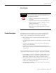
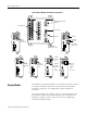
Powermonitor 3000 Figure 3 Master Module with Communication Options Removable Status Input Connector Terminal Blocks LED Indicators Powermonitor wermonitor 3000 Powermonitor wermonitor 3000 NAP Port Display Module Port ControlNet Channel A Optional RS-232 Port ControlNet Channel B RS-485 (Native) Communications Port Powermonitor wermonitor 3000 Powermonitor wermonitor 3000 Optional Remote I/O Port Display Module Powermonitor wermonitor 3000 Optional DeviceNet Port Auxiliary Port (not u
Powermonitor 3000 11 The Display Module is shipped with a 3-meter (10 ft) long, shielded 4-pair cable that provides power and serial communications between the Master Module and the Display Module. The Display Module fits into a standard ANSI four inch analog meter cutout for panel mounting. Only one Display Module may be connected to a Master Module, although you may use one Display Module to configure and monitor any number of Master Modules; one at a time.
Powermonitor 3000 Table 7 Native RS-485 Communications only (catalog numbers ending in -000) Powermonitor 3000 F1 F2 LED LED Color LED State and Communications Condition F1 Off Not Used F2 Off Not Used F3 Off Not Used F3 Table 8 RS-232 Optional Communications (catalog numbers ending in -232) Powermonitor 3000 LED LED Color LED State and Communications Condition F1 Off Not Used RS-232 RX Off The RS-232 bus is idle; no active data is present Flashing Green Powermonitor 3000 is r
Powermonitor 3000 13 Table 10 DeviceNet Optional Communications (catalog numbers ending in -DNT) LED LED Color LED State and Communications Condition F1 Off Not Used F2 Off Not Used NETWORK STATUS Off Power is off or the Powermonitor 3000 is not online F1 Flashing Green Network status is OK, no connections established F2 Steady Green NETWORK STATUS Network status is OK, connections established Flashing Red Recoverable communications failure; port is restarting Steady Red Non-recovera
Powermonitor 3000 Table 12 Ethernet/IP Optional Communications (Series B catalog numbers ending in -ENT) Powermonitor 3000 LED LED Color LED State and Communications Condition LNK Off No valid physical Ethernet connection Steady Green Valid physical Ethernet connection Strobing or Powermonitor 3000 transmitting onto Ethernet LNK ACT F1 ACT F2 NETWORK STATUS Solid Yellow F1 Off Not Used F2 Off Not Used NETWORK STATUS Off No power Flashing Green No established connections Steady
Powermonitor 3000 Quick Start Guidelines 15 The Powermonitor 3000 may be used in many electric power monitoring and control systems. Whether your Powermonitor 3000 is a complete power and energy monitor or a component in a plant- or enterprise-wide energy management system, there are a few basic steps to follow to make your unit operational. 1. Install your Powermonitor 3000 master module within a suitable enclosure. Refer to Installation on page 15. 2. Install your optional Display Module.
Powermonitor 3000 Prevent Electrostatic Discharge ATTENTION Electrostatic discharge can damage integrated circuits or semiconductors. Follow these guidelines when you handle the module. • Touch a grounded object to discharge static potential. • Wear an approved wrist strap grounding device. • Do not open the module or attempt to service internal components. • If available, use a static safe work station. • When not in use, keep the module in its static shield bag.
Powermonitor 3000 IMPORTANT 17 Use caution not to block the ventilation slots of the Master Module. All wiring and other obstructions must be a minimum of 50 mm (2.0 inches) from the top and bottom of the unit. See Figure 41 on page 56 for mounting hole dimensions. Mount the Master Module with four (4) No. 8-32 UNC or M4 screws with flat washers and lock washers.
Powermonitor 3000 For a PT the Ratio Error increases as the transformer’s load current increases, so its total load impedance should be as high as possible. Conversely, a CT’s Ratio Error increases as the voltage supported by the transformer secondary increases, so its total load impedance, including the impedance of the wire connecting the CTs to the metering device, should be as low as possible. This is why #12 AWG or larger is usually recommended for wiring CTs with a 5 amp secondary rating.
Powermonitor 3000 19 Bandwidth Error For fundamental 50 Hz or 60 Hz measurements, bandwidth error has no affect on accuracy. However, for waveforms with significant harmonic content, the user-supplied PTs and CTs may attenuate higher harmonics. Most instrument quality PTs have a flat frequency response out to 3 kHz, or the 50th harmonic on a 60 Hz system. Current transformers, especially older, existing units, tend to be less linear, with a flat response only out to 300 Hz, or the fifth (60 Hz) harmonic.
Powermonitor 3000 • Install and connect all wiring in a neat and workmanlike manner. Use wire tags to identify connections. Bundle wiring neatly and maintain a minimum of 50 mm (2.0 inches) clearance from the Master Module ventilation slots to avoid a buildup of heat within the unit • Furnish and install properly-selected fuses for voltage signals and control power • Use 600 volt wiring rated at 75°C (167°F) or higher.
Powermonitor 3000 21 Voltage and Current Inputs Voltage Input and PT Selection The Powermonitor 3000 is designed to connect directly to power system rated up to 600 volts line-to-line (347 volts line-to-neutral). Higher system voltages require the use of user-supplied PTs. Typical secondary voltage on a PT is 120V ac. Select the PT primary voltage to match the nominal voltage of your power system. Connect user-furnished short circuit protection between the power system and the Powermonitor 3000.
Powermonitor 3000 IMPORTANT You may install either two or three CTs for any of the Delta or Open Delta wiring or voltage modes. Refer to Figure 21, Figure 23, or Figure 26 for wiring of a 2 CT configuration. Whether there are two or three CTs in a circuit does not affect the voltage wiring. Refer to the User Manual, publication 1404-UM001. Do not install fuses or other overcurrent protection in the secondary circuit of a CT.
Powermonitor 3000 Wiring Diagrams 23 Figure 14 Single Phase Direct Connection Wiring Diagram (Systems < 600 Volts Nominal L-L) Voltage Mode = Single Phase Line L1 L2 N Fuse Fuse Customer Supplied CT Shorting Switch or Test Block Powermonitor 3000 MASTER MODULE R14 R11 R12 N/C I1I2I3I4- Y Z N/C V1 I1+ V2 I2+ V3 I3+ N I4+ R14 R11 R12 Y Load L1 (+) L2 (-) GRD K K Z Customer Chassis Ground Publication 1404-IN007D-EN-P - October 2004
Powermonitor 3000 Figure 15 Single Phase with PTs Wiring Diagram Line L1 L2 Voltage Mode = Single Phase N Fuse Fuse Customer Supplied CT Shorting Switch or Test Block R14 R11 R12 N/C I1I2I3I4- Y Publication 1404-IN007D-EN-P - October 2004 Customer Chassis Ground L1 (+) L2 (-) GRD K Z N/C V1 I1+ V2 I2+ V3 I3+ N I4+ R14 R11 R12 Y Load Powermonitor 3000 MASTER MODULE K Z
Powermonitor 3000 25 Figure 16 3-Phase 4-Wire Wye Direct Connect Wiring Diagram (Systems < 600 Volts Nominal L-L) Line L1 L2 L3 Voltage Mode = Wye N Fuse Fuse Fuse Customer Supplied CT Shorting Switch or Test Block R14 R11 R12 N/C I1I2I3I4- Y L1 (+) L2 (-) GRD K Z N/C V1 I1+ V2 I2+ V3 I3+ N I4+ R14 R11 R12 Y Load Powermonitor 3000 MASTER MODULE K Z Customer Chassis Ground Publication 1404-IN007D-EN-P - October 2004
Powermonitor 3000 Figure 17 3-Phase 4-Wire with PT’s Wiring Diagram Line L1 L2 L3 Voltage Mode = Wye N Fuse Fuse Fuse Customer Supplied CT Shorting Switch or Test Block R14 R11 R12 N/C I1I2I3I4- Y Load Publication 1404-IN007D-EN-P - October 2004 L1 (+) L2 (-) GRD K Z N/C V1 I1+ V2 I2+ V3 I3+ N I4+ R14 R11 R12 Y Customer Chassis Ground Powermonitor 3000 MASTER MODULE K Z
Powermonitor 3000 27 Figure 18 3-Phase 3-Wire Grounded Wye Direct Connection Wiring Diagram (Systems < 600 Volts Nominal L-L) Line L1 L2 Voltage Mode = Wye L3 Fuse Fuse Fuse Customer Supplied CT Shorting Switch or Test Block R14 R11 R12 N/C I1I2I3I4- Y L1 (+) L2 (-) GRD K Z N/C V1 I1+ V2 I2+ V3 I3+ N I4+ R14 R11 R12 Y Load Powermonitor 3000 MASTER MODULE K Z Customer Chassis Ground Publication 1404-IN007D-EN-P - October 2004
Powermonitor 3000 Figure 19 3-Phase 3-Wire Grounded Wye with PT’s Wiring Diagram Line L1 L2 Voltage Mode = Wye L3 Fuse Fuse Fuse Customer Supplied CT Shorting Switch or Test Block R14 R11 R12 N/C I1I2I3I4- Y Load Publication 1404-IN007D-EN-P - October 2004 L1 (+) L2 (-) GRD K Z N/C V1 I1+ V2 I2+ V3 I3+ N I4+ R14 R11 R12 Y Customer Chassis Ground Powermonitor 3000 MASTER MODULE K Z
Powermonitor 3000 29 Figure 20 3-Phase 3-Wire Delta with Three PT’s and Three CT’s Wiring Diagram Line Voltage Mode = Delta 3 CT L1 L2 L3 Fuse Fuse Fuse Customer Supplied CT Shorting Switch or Test Block R14 R11 R12 N/C I1I2I3I4- Y L1 (+) L2 (-) GRD K Z N/C V1 I1+ V2 I2+ V3 I3+ N I4+ R14 R11 R12 Y Load Powermonitor 3000 MASTER MODULE K Z Customer Chassis Ground Publication 1404-IN007D-EN-P - October 2004
Powermonitor 3000 Figure 21 3-Phase 3-Wire Delta with Three PT’s and Two CT’s Wiring Diagram Voltage Mode = Delta 2 CT Line L1 L2 L3 Fuse Fuse Fuse Customer Supplied CT Shorting Switch or Test Block R14 R11 R12 N/C I1I2I3I4- Y Publication 1404-IN007D-EN-P - October 2004 Customer Chassis Ground L1 (+) L2 (-) GRD K Z N/C V1 I1+ V2 I2+ V3 I3+ N I4+ R14 R11 R12 Y Load Powermonitor 3000 MASTER MODULE K Z
Powermonitor 3000 31 Figure 22 3-Phase 3-Wire Open Delta with Two PT’s and Three CT’s Wiring Diagram Voltage Mode = Open Delta 3 CT Line L1 L2 L3 Fuse Fuse Customer Supplied CT Shorting Switch or Test Block R14 R11 R12 N/C I1I2I3I4- Y L1 (+) L2 (-) GRD K Z N/C V1 I1+ V2 I2+ V3 I3+ N I4+ R14 R11 R12 Y Load Powermonitor 3000 MASTER MODULE K Z Customer Chassis Ground Publication 1404-IN007D-EN-P - October 2004
Powermonitor 3000 Figure 23 3-Phase 3-Wire Open Delta with Two PT’s and Two CT’s Wiring Diagram Voltage Mode = Open Delta 2 CT Line L1 L2 L3 Fuse Fuse Customer Supplied CT Shorting Switch or Test Block R14 R11 R12 N/C I1I2I3I4- Y Publication 1404-IN007D-EN-P - October 2004 Customer Chassis Ground L1 (+) L2 (-) GRD K Z N/C V1 I1+ V2 I2+ V3 I3+ N I4+ R14 R11 R12 Y Load Powermonitor 3000 MASTER MODULE K Z
Powermonitor 3000 33 Figure 24 3-Phase 3-Wire Grounded L2(B) Phase Open Delta Direct Connect with Three CT’s Wiring Diagram(Systems < 600 Volts Nominal L-L) Voltage Mode = Open Delta 3 CT Line L1 L3 Distribution Ground Fuse Fuse Voltage must not exceed 347 Volts L-L (otherwise, step down transformers are required).
Powermonitor 3000 Figure 25 3-Phase 3-Wire Delta Direct Connect with Three CT’s Wiring Diagram (Systems < 600 Volts Nominal L-L) Voltage Mode = Direct Delta 3 CT Line L1 L2 L3 Fuse Fuse Fuse Customer Supplied CT Shorting Switch or Test Block R14 R11 R12 N/C I1I2I3I4- Y Load Publication 1404-IN007D-EN-P - October 2004 L1 (+) L2 (-) GRD K Z N/C V1 I1+ V2 I2+ V3 I3+ N I4+ R14 R11 R12 Y Customer Chassis Ground Powermonitor 3000 MASTER MODULE K Z
Powermonitor 3000 35 Figure 26 3-Phase 3-Wire Delta Direct Connect with Two CT’s Wiring Diagram (Systems < 600 Volts Nominal L-L) Line L1 L2 Voltage Mode = Direct Delta 2 CT L3 Fuse Fuse Fuse Customer Supplied CT Shorting Switch or Test Block R14 R11 R12 N/C I1I2I3I4- Y L1 (+) L2 (-) GRD K Z N/C V1 I1+ V2 I2+ V3 I3+ N I4+ R14 R11 R12 Y Load Powermonitor 3000 MASTER MODULE K Z Customer Chassis Ground Publication 1404-IN007D-EN-P - October 2004
Powermonitor 3000 Control Power Figure 27 Control Power The Powermonitor 3000 draws a nominal 15VA control power. Catalog numbers 1404-MxxxA-xxx require nominal control power of 120 to 240V ac or 125 to 250V dc. The power supply is self-scaling. Catalog number 1404-MxxxB-xxx require nominal control power of 24V dc. Refer to Technical Specifications on page 59 for acceptable control voltage ranges and wiring termination information.
Powermonitor 3000 37 Figure 28 Status Input Connections N.O. Contact Powermonitor 3000 MASTER MODULE Y R14 K L1 (+) Z L2 (-) R11 R12 N/C N.O. Contact S1 S2 SCOM GRD N/C V1 I1+ I1- V3 N I3- Condition 2 Applied resistance verses status state 3.5K Ohms or less = ON 5.5K Ohms or greater = Off SHLD + I4+ I4R14 R11 R12 Condition 1 Isolation Voltage 500V status input to case; 500V status input to internal digital circuitry.
Powermonitor 3000 Communication Wiring Methods for connecting communications wiring vary from option to option. This section provides guidelines for installing dependable communications wiring for your Powermonitor 3000 system for each communications option including the native RS-485 communications port that is part of every Powermonitor 3000. ATTENTION IMPORTANT The user must supply and install special high level isolation when the possibility of high ground potential differences exists.
Powermonitor 3000 39 If required, install suitable terminating resistors at the ends of the daisy-chain cable. For RS-485, install a 150 ohm, 1/4 watt terminating resistor (refer to the wiring diagram). Note that some RS-485 conversion devices are equipped with internal terminating resistors. Contact the manufacturer of the converter for additional information. At each end of each cable segment, connect the cable shields to the SHLD terminal of the Master Module RS-485 port or the converter.
Powermonitor 3000 Figure 31 RS-485 Connections IBM Compatible PC Shield Connection (See Note 4) External RS-232C to RS-485 Converter (See Note 3) SHLD A B 150Ω Terminating Resistor (See Note 2) Or PLC Processor Powermonitor 3000 Device #1 SHLD Or SLC Processor RS-485 _ + Powermonitor 3000 Device #2 Or ControlLogix Processor SHLD RS-485 _ + Notes: 1) 3-device network portrayed.
Powermonitor 3000 41 Optional RS-232 Communications Powermonitor 3000 units with a catalog number ending in -232 are equipped with an RS-232 serial communications port in addition to the native RS-485 port. The RS-232 communications standard supports point-to-point communications among two stations or nodes. The RS-232 port supports Allen-Bradley DF1 half-duplex slave and Modbus RTU slave communications at data rates of 1200 to 19.2k baud.
Powermonitor 3000 Figure 32 Connecting Powermonitor 3000 to Computer Communications Port Powermonitor 3000 DB9 Female 5 1 6 9 RS-232 IBM Compatible PC no connect 1 – TXD 2 output input RXD 3 no connect 4 – GND 5 ground DSR (See Note 2) 6 output RTS (See Note 1) 7 CTS (See Note 1) 8 no connect 9 input output – (See Note 3) Notes: 1) Required only if user has enabled hardware handshaking. 2) Internally pulled active in this DCE device - function not supported.
Powermonitor 3000 43 Table 33 and varies with the data rate. Use of a star or bridging topology is not recommended and will result in signal distortion unless impendance is matched for each spur (star topology) or network (bridge topology). Ensure that all devices on your Remote I/O network are capable of operation at the desired baud rate. Certain legacy devices may not support a 230.4k baud rate. Table 33 Remote I/O Capabilities Baud Rate Maximum Distance Terminating Resistor 57.
Powermonitor 3000 Figure 34 Connecting Powermonitor 3000 to Remote I/O Scanner IBM Compatible PC With R I/O Interface Card 82 ohm Terminating Resistor (See Note 2) Blue Shield 1 SHLD Or PLC Processor/ PLC R I/O Scanner Clear 2 Powermonitor 3000 Device #1 2 SHLD R I/O 1 Or SLC R I/O Scanner Powermonitor 3000 Device #2 2 Or ControlLogix R I/O Scanner SHLD R I/O Notes: 1) 3-Device Network portrayed. Up to 32 slave devices can be connected per master R I/O channel.
Powermonitor 3000 45 Optional DeviceNet Communications Powermonitor 3000 units with a catalog number ending in -DNT are equipped with a DeviceNet port in addition to the native RS-485 port. DeviceNet is an open-standard, multi-vendor, industrial device data network that uses a variety of physical media. DeviceNet also provides 24V dc power to devices connected to the network. The DeviceNet port and the native RS-485 port may be used simultaneously, although overall data throughput may be reduced.
Powermonitor 3000 Figure 36 Connecting Powermonitor 3000 to other DeviceNet Devices VPowermonitor 3000 Device CAN_L SHLD CAN_H 121 ohm Terminating Resistor (See Note 2) V+ Cabling: Allen-Bradley catalog number: 1485C-P1-C (thin cable - DeviceNet) IBM Compatible PC With 1784 PCDPCMCIA Interface Card Or 1770-KFD Interface Box VCAN_L SHLD CAN_H Or PLC With 1771-SDN Scanner V+ VCAN_L SHLD CAN_H V+ Or SLC With 1747-SDN Scanner VCAN_L SHLD CAN_H Or other DeviceNet scanner devices Notes: 1) Example
Powermonitor 3000 47 Table 37 Ethernet Hardware Versions Series A Series B Data Rate 10M Bit only 10/100M bit Protocol Supported EtherNet/IP and CSP EtherNet/IP Built-in Web Page Yes, fixed Yes, configurable Supports CIP Class 1 Connnection (I/O Data) No Yes Supports Control FLASH No Yes The Powermonitor 3000 is designed to connect easily to industry-standard Ethernet hubs and switches using standard UTP (unshielded twisted-pair) cables with RJ-45 connectors.
Powermonitor 3000 Figure 39 Powermonitor 3000 Ethernet Network Example Ethernet Switch LAN SLC 500 Controller Powermonitor 3000 Master Module #1 PC w/RSLinx and RSPower 32 or RSEnergyMetrix PLC 5 Controller Powermonitor 3000 Master Module #2 ControlLogix Controller Refer to the note at the beginning of Communication Wiring page 38. Configuration options for optional Ethernet communications include the IP (Internet Protocol) address, subnet mask, default gateway IP address and protocol.
Powermonitor 3000 49 Optional ControlNet Communications Powermonitor 3000 units with catalog numbers ending in -CNT are equipped with a ControlNet communications interface. The ControlNet Powermonitor 3000 can be connected in a single media or redundant media network. Figure 40 shows an example ControlNet network using redundant media.
Powermonitor 3000 Connecting a Programming Terminal to the Network Using 1786-CP Cable To connect a programming terminal to the network using a 1786-CP cable, you have the following options: 1. Using a 1784-KTC, -KTCx, or -PCC communication card and a 1786-CP cable: Powermonitor 3000 Device 1786-CP Cable 1784-KTC, KTCx, PCIC, or PCC card ControlNet link 2.
Powermonitor 3000 ATTENTION Maintenance 51 Use a 1786-CP cable when connecting a programming terminal to the network through NAPs. Using a commercially available RJ-style cable could result in network failure. Accessing Self-test/Diagnostic Data using Display Module You can access valuable diagnostic information using the optional Display Module. Connect the Display Module to the Master Module using the Display Module cable.
Powermonitor 3000 • - displays the optional communications status bitfield as a hex number (0000 hex is normal for -232 and -RIO units, and 9001 hex is normal for -DNT and -ENT units). • - displays the Display Module status bitfield as a hex number. A non-zero value may indicate a problem, although a non-zero value may appear if a Display Module is connected to an operating Master Module. • - indicates the Display Module firmware revision. • - displays the current Date.
Powermonitor 3000 53 Cleaning Instructions ATTENTION Electrostatic discharge can damage integrated circuits or semiconductors. Follow these guidelines when you handle the module. • Touch a grounded object to discharge static potential. • Wear an approved wrist strap grounding device. • Do not open the module or attempt to service internal components. • If available, use a static safe work station. • When not in use, keep the module in its static shield bag.
Powermonitor 3000 Field Service Considerations If the Powermonitor 3000 requires servicing, please contact your nearest Allen-Bradley Sales Office. To minimize your inconvenience, the initial installation should be performed in a manner which makes removal easy. 1. A CT shorting block should be provided to allow the Powermonitor 3000 Master Module current inputs to be disconnected without making the user-supplied CT’s an open circuit.
Powermonitor 3000 55 installation. An RS-485 to RS-232 converter is required to connect between the Powermonitor 3000 and your personal computer communications port. Cycling power to the Powermonitor 3000 may be required to complete the firmware upgrade. Factory-Installed Communication Cards The RS-485 communications is integral to the Master Module and can not be removed. Adding or changing a second communication card to a Powermonitor 3000 must be done at the factory and is not field upgradeable.
Powermonitor 3000 Dimension Drawings Figure 41 Master Module Dimensions 14.66 (0.577) 5.35 (0.211) 114.30 (4.50) 85.0 (3.346) Mounting 4.57 (0.180) 4 Places 10.43 (0.411) Powermonitor 3000 125.0 (4.921) Mounting 135.15 (5.321) 114.30 (4.50) 184.15 (7.250) Used With Display Module 163.17 (6.424) Used Without Display Module 203.2 (8.000) Used With -232 Communications Options 5.60 (0.22) All dimensions are in mm (inches). Figure 42 Master Module Spacing 215.9 (8.50) (See Note 1) 50.8 (2.
Powermonitor 3000 Product Approvals 57 EtherNet/IP Conformance Testing All Series B Powermonitor products equipped with an EtherNet/IP communications port bear the mark shown below. This mark indicates the Powermonitor 3000 has been tested at an Open Device Vendor Association (ODVA) independent test lab and has passed the EtherNet/IP conformance test.
Powermonitor 3000 CE Certification If this product bears the CE marking, it is approved for installation within the European Union and EEA regions. It has been designed to meet the following directives.
Powermonitor 3000 59 ANSI/IEEE Tested Meets or exceeds the Surge Withstand Capability (SWC) C37.90.1 1989 for protective relays and relay systems on all power connection circuit terminations. Technical Specifications Measurement Accuracy and Range See table below for the rating of each parameter Table 43 Measurement Accuracy and Range Parameter Voltage Sense Inputs: V1, V2, V3 Accuracy in % of Full Scale at +25°C 50/60 Hz Unity Power Facator M4 M5 M6 M8 ±0.2% ±0.05% ±0.05% ±0.
Powermonitor 3000 Table 44 Input and Output Ratings Current Sense Inputs: I1, I2, I3, I4 Overload Withstand: 15 Amps Continuous, 200 Amps for one second Burden: 0.05 VA Impedance: 0.002 ohms Maximum Crest Factor at 5A is 3 Starting Current: 5 mA Status Inputs Contact Closure (Internal 24Vdc) Control Relay KYZ Output (1) ANSI C37.
Powermonitor 3000 61 Table 47 General Specifications Dielectric Withstand Terminal Blocks Control Power 2000 Volts Voltage Inputs 2000 Volts Current Inputs 2000 Volts Status Inputs 500 Volts Control Relays 1600 Volts Power Supply and Voltage input Terminals 12 AWG (4 mm2) max., 9 lb-in (1.02 Nm) Torque., 75°C or Higher Copper Wire only Relay, KYZ outputs, Current input terminals(1) 14 AWG (2.5 mm2) max., 10.4 lb-in (1.18 Nm) Torque.
Powermonitor 3000 Publication 1404-IN007D-EN-P - October 2004
Index C P calibration 1-52 catalog number explanation 1-55 cleaning instructions 1-53 control power 1-36 D device configuration 1-8 display module 1-10 E electrostatic discharge 1-16, 1-36 F factory-installed communication cards 1-55 field service considerations 1-54 firmware upgrades 1-54 I installation 1-15 L LED indicators 1-11 M maintenance 1-51 calibration 1-52 factory-installed communication cards 1-55 field service considerations 1-54 firmware upgrades 1-54 self-test diagnostic data 1-51 ma
2 Index status inputs 1-36 terminal blocks wire sizes and screw torques 1-20 voltage and current inputs 1-21 wiring diagrams 1-23 3-phase 3-wire delta direct connect with three CTs 1-35 3-phase 3-wire delta with three PTs and three CTs 1-31 3-phase 3-wire grounded L2 (B) phase open delta direct connect with three CTs 1-34 3-phase 3-wire grounding wye direct connection 1-28 Publication 1404-IN007D-EN-P - October 2004 3-phase 3-wire grounding wye with PTs 1-29 3-phase 3-wire open delta with three PTs and
Rockwell Automation Support Rockwell Automation provides technical information on the web to assist you in using our products. At http://support.rockwellautomation.com, you can find technical manuals, a knowledge base of FAQs, technical and application notes, sample code and links to software service packs, and a MySupport feature that you can customize to make the best use of these tools.