
Instruction Sheet User guide

Smart Communications Card
8
Publication
1403-5.1
General Operation
Communications Card Set-Up
All
communications card options such as
communications format, baud rate, address, etc., are set
by configuring the Master Module. Refer to
Powermonitor II Instruction Sheet
, Publication 1403-5.0,
Chapter 4.
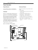
Indicators
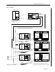
Figure 1. on page 2 shows the location of the LED
Indicators on the communications card.
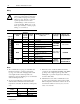
Table B. LED Indicators
LED
Location
LED
Color
Port Assignment LED State and Communications Condition
Top Red RS-232 or RS-485 Receive
OFF = Idle
ON/OFF Pulsing = Receiving Data
Middle Red RS-232 or RS-485 Transmit
OFF = Idle
ON/OFF Pulsing = Transmitting Data
Bottom Green
R I/O
ON = Communications Established
ON/OFF Blinking = Communications Established With Some Errors
OFF = Communications Not Established
Configuration
Items
Communication
Table C. Communication Configuration Items
Parameter
Description Range Default
User
Setting
R I/O Rack Address
Specifies the logical rack of the Smart Communication
Card.
0 to 63 1
R I/O Group Number Determines the group number of the logical rack.
0 = First Quarter
2 = Second Quarter
4 = Third Quarter
6 = Fourth Quarter
0 = First
Quarter
R I/O Last Rack
Defines whether or not the configured rack is the last
rack.
0 = No
1 = Yes
0 = No
R I/O Baud Rate Specifies the baud rate of the RIO network.
0 to 56K
1 to 115K
2 to 230K
0 to 56K
Serial Delay
Defines the delay in ms between the request and
response serial packets.
0 to 15 0
Serial Mode Specifies the serial communications mode.
0 = RS-485
1 = RS-232
1 = RS-232
RS-232/RS-485 Baud
Rate
Determines the baud rate for the serial communications.
0 to 1200
1 to 2400
2 to 4800
3 to 9600
4 to 19200
3 to 9600
Serial Device Identifier
Defines the specific serial address. A value of 255 is
used as a broadcast address.
0 to 254 Device ID#