
Instruction Sheet User guide


7
Smart Communications Card
Publication
1403-5.1
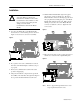
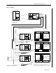
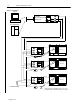
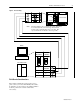
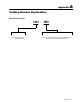
Figure 7. RS-232C Wiring
IBM PC
PLC PROCESSOR
1
3
2
7
CASE
GROUND
2
3
5
25 PIN
D–SHELL
9 PIN
D–SHELL
Powermonitor
II
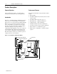
Note: For
CE compliance, the communication cable shield must
be connected directly to the chassis ground terminal
located on the communication card cover plate. The
exposed shield wire should be as short as possible.
Field Service Considerations
If the Smart Communications Card requires service,
please contact your nearest Allen-Bradley Sales Of
fice.
To minimize your inconvenience, the initial installation
should be performed in a manner which makes
removal easy
.