
Instruction Sheet User guide
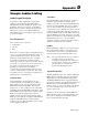
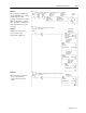
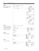
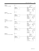
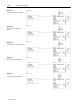

D–2 Sample Ladder Listing
Publication
1403-5.1
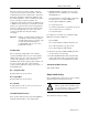
The SLC-500 R I/O version requires that all read and
write tables be 64 words in length. This is a necessary
requirement stemming from the use of the block transfer
subroutines.
A four word length control file needs to be initialized for
each individual block transfer subroutine. The
initialization values for each word are discussed in the
Data Files Used section.
SLC-500 RS-232 Operation
Use of an SLC-500 MSG instruction in place of the BTW
and BTR instructions is the only dif
ference between the
PLC-5 R I/O and the SLC-500 RS-232 versions of the
Powermonitor II sample ladder.
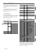
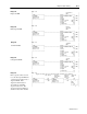
PLC-5 R I/O Data Files Used
Data File
Address
Data File
Size
Description
B3 20 b3/0 Configuration mode enable
b3/2 Run mode enable
b3/1 Setpoint mode enable
b3/300 One-shot bit
b3/301 One-shot bit
b3/302 One-shot bit
b3/303 One-shot bit
b3/304 One-shot bit
N9 1 N9:0 Sequencer output
N10 variable N10:0 Sequencer input
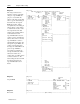
Data File
Address
Data File
Size
Description
N11 3 N11:0 Sequencer input data for
configuration mode
N12 3 N12:0 Sequencer input data for
setpoint mode
N13 variable N13:0 Sequencer input data for
run mode
N20 2 N20:0 Number of setpoints
N20:1 Temporary storage for
setpoint address
N22 21 Setpoint #1 location
N23
•
•
•
21 Setpoint #2 location
•
•
•
N39 21 Setpoint #20 location
R6:0 Sequencer control
BTR Data Table Locations
(control / data)
N40 / N70 54 Voltage/current data
N41 / N71 63 Real-time power
N42 / N72 46 Cumulative power
N43 / N73 45 Device configuration
N44 / N74 31 Communication configuration
N45 / N75 43 Demand
N46 / N76 61 Even harmonic distortion
N47 / N77 62 Odd harmonic distortion
N48 / N78 59 Even harmonic magnitude
N49 / N79 58 Odd harmonic magnitude
N50 / N80 57 Even harmonic phase
N51 / N81 56 Odd harmonic phase
N52 / N82 40 Diagnostic
N53 / N83 39 Relay/setpoint
BTW Data Table Locations
(control / data)
N54 / N84 23 Command
N55 / N85 45 Device configuration
N56 / N86 21 Setpoint
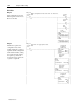
Sequencer input file N10 contains a list of the block
transfers required to complete the active mode. The
contents of N10 are copied from N11 for Configuration
mode, N12 for Setpoint mode and N13 for Run mode
during each mode’
s initialization.