
Instruction Sheet User guide

B–5Smart Communication Card Data Tables
Publication
1403-5.1
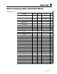
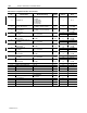
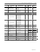
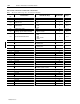
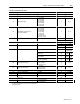
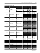
Table B.4 Command Data Table Write
Parameter No. Parameter Name Master Module Range Word No. Range
3.1 Command Word 1 (Bit Fields) 0 to 2047 1 0 to 2047
3.2 Command Word 2 (Bit Fields) 0 to 511 2 0 to 511
3.3 Harmonic Analysis
➀
1 = L1 Voltage
2 = L1 Current
3 = L2 Voltage
4 = L2 Current
5 = L3 Voltage
6 = L3 Current
7 = L4 Current
3 1 to 7
3.4
Oscillogram Channel Request
➀
(Reserved 1403-LM)
1 = L1 Voltage
2 = L1 Current
3 = L2 Voltage
4 = L2 Current
5 = L3 Voltage
6 = L3 Current
7 = L4 Current
8 = Ch–A 12 Cycle
9 = Ch–B 12 Cycle
4 1 to 9
3.5 W Hour Data for Set Command
➀
–9999x10
8
to +9999x10
8
5 –9999 to 9999
6
10
±
0
to
21
3.6 VAR Hour Data for Set Command
➀
–9999x10
8
to +9999x10
8
7 –9999 to 9999
8
10
±
0
to
21
3.7 Reserved 9 9
10 10
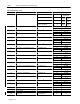
3.8 Time for Set Command
➀
Year 11
0–99
16 Bit Integer
Month, Day 12
1–12
8 Bit
1–31
8 Bit
Hour, Minutes 13
0–23
8 Bit
0–59
8 Bit
Seconds, Hundredths 14
0–59
8 Bit
0–99
8 Bit
3.9 Force Specifics Relay 1
➀
1 = Energize
2 = De-energize
4 = Remove Force
15 1, 2, 4
3.10 Force Specifics Relay 2
➀
1 = Energize
2 = De-energize
4 = Remove Force
16 1, 2, 4
3.11 Setpoint Number
➀
1 to 20 17 1 to 20
3.12 Present Unit Password 0 to 9999 18 0 to 9999
Reserved 19
Reserved 20
Reserved 21
3.13 Data Format
0 = Integer/Exponent
1 = Floating Point
22 0 to 1
➀
See T
able B.5 in Publication 1403-5.1 for specific command bits to
enable these features.