
Instruction Sheet User guide
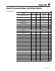

B–3Smart Communication Card Data Tables
Publication
1403-5.1
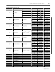
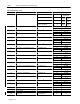
Parameter
No.
Parameter Name Master Module Range
Default
Setting
Word No. Range
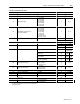
Reserved Word 0 27
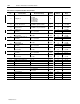
1.19 Output Pulse Relay No.
0 = None
1 = Relay 1
2 = Relay 2
0 28 0 to 2
1.20 Output Pulse Parameter
0 = kWh Forward
1 = kWh Reverse
2 = kVarh Forward
3 = kVarh Reverse
0 29 0 to 3
1.21 Output Pulse Increment 1 to 32766 1 30 1 to 32766
1.22 Output Pulse Width (ms) 40 to 2000 100 31 40 to 2000
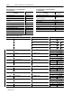
1.23 Ch A 12 Cycle Oscillogram
1 = Phase 1 Voltage
2 = Phase 1 Current
3 = Phase 2 Voltage
4 = Phase 2 Current
5 = Phase 3 Voltage
6 = Phase 3 Current
7 = Phase 4 Current
1 32 1 to 7
1.24 Ch B 12 Cycle Oscillogram
1 = Phase 1 Voltage
2 = Phase 1 Current
3 = Phase 2 Voltage
4 = Phase 2 Current
5 = Phase 3 Voltage
6 = Phase 3 Current
7 = Phase 4 Current
2 33 1 to 7
1.25 Oscillography Type
0 = Hold
1 = Overwrite
1 34 0 to 1
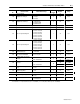
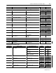
1.26
Number of Pretrigger Cycles for
the 12 Cycle Oscillogram
–1 = No Pretrig
0 to +8 = Cycles
0 35 –1 to +8
1.27
IEEE 519 Max. Short Circuit
Current
0
36 0 to 9999
0.0 to 10,000,000.0
0
37
10
±
0
to
21
1.28
IEEE 519 Max. Demand/Load
Current
0
38 0 to 9999
0.0 to 10,000,000.0
0
39
10
±
0
to
21
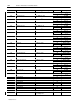
1.29
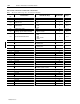
Save Status Changes to Event
Log
0 = No
1 = Yes
0 40 0 to 1
1.30 Vaux Voltage Mode
0 = AC
1 = DC
0 41 0 to 1
1.31 Enable THD 0 or 1 1 42 0 to 1
1.32 Enable Min_Max Log
0 = No
1 = Yes
1 43 0 to 1
1.33 Data Format
0 = Integer/Exponent
1 = Floating Point
0 44 0 to 1
➀
This
value will be 1 for 1 Amp Master Module (Cat. No. 1403-MM01X) or 5 for a 5 Amp Master Module (Cat. No. 1403-MM05X).