
Instruction Sheet User guide

B–2 Smart Communication Card Data Tables
Publication
1403-5.1
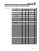
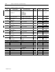
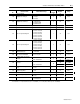
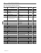
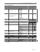
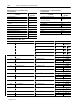
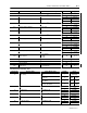
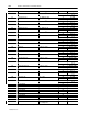
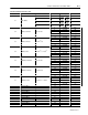
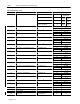
Table B.2 Device Configuration Data Table – Write and Read
Parameter
No.
Parameter Name Master Module Range
Default
Setting
Word No. Range
1.1 Voltage Mode
0 = Demo
1 = Single
2 = Open Delta
3 = 3-Wire Delta
4 = 4-Wire Wye
5 = Direct Delta
4 1 0 to 5
1.2 Present Unit Password
–1 is always returned on a Read
0 to 9999 is required for a Write
0 2 –1 to +9999
1.3 New Password
–1 does not change the password
0 to 9999 is new password value
0 3 –1 to +9999
1.4 Voltage Scale
120 0
4 0 to 9999
PT Primary 1.0 to 10,000,000.0
120.0
5
10
±
0
to
21
1.5 Voltage Scale
PT Secondary 1 to 999 120 6 1 to 999
1.6 Current Scale (For I1, I2, I3)
1or5
➀
7 0 to 9999
CT Primary 1.0 to 10,000,000.0
1 or 5
➀
8
10
±
0
to
21
1.7 Current Scale (For I1, I2, I3)
CT Secondary 1 to 999 1 or 5
➀
9 1 to 999
1.8 Analog Input Scale
10
10 0 to 9999
PT Primary 1.0 to 10,000,000.0
1.0
11
10
±
0
to
21
1.9 Analog Input Scale
PT Secondary 1 to 999 1 12 1 to 999
1.10 Neutral Current Scale (For I4)
1or5
➀
13 0 to 9999
CT Primary 1.0 to 10,000,000.0
1 or 5
➀
14
10
±
0
to
21
1.11 Neutral Current Scale (For I4)
CT Secondary 1 to 999 1 or 5
➀
15 1 to 999
1.12 Demand Period Length –99 to +99 1 16 –99 to +99
1.13 Number of Demand Periods 1 to 15 1 17 1 to 15
1.14 Reserved Word 0 18
1.15 Snapshot Interval – Hours 0 19 0 to 32,767
1.16 Snapshot Interval – Minutes 0 20 0 to 32,767
1.17 Snapshot Interval – Seconds 0 21 0 to 32,767
1.18 Snapshot Buffer Type
0 = Fill and Stop
1 = Circular
1 22 0 to 1
Reserved Word 0 23
Reserved Word 0 24
Reserved Word 0 25
Reserved Word 0 26