
Installation Instructions Owner's manual

Publication 1403-IN005A-EN-P
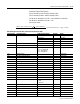
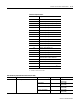
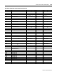
B-38 Ethernet Communication Card Data Tables
20.25 Display Module No. 2 FRN 0 to 32767 28 0 to 32767
20.26 Display Module No. 3 FRN 0 to 32767 29 0 to 32767
20.27 Auxiliary Frequency
0 to 9999x10
21
30 0 to 9999
31 0 to 32
20.28 Fiber Loop Back Test Results 0 = Fail
1 = Pass
32 0 to 1
20.29 EEPROM Status 33 16-bit Integer
20.30 Device ID 0 to 255 34 0 to 255
20.31 General Purpose Status Bits bit 0 = oscillograph capture #1
ready to be read
bit 1 = snapshot buffer full
bit 2 = oscillogram capture #1
triggered by a setpoint
bit 3 = oscillograph capture #2
ready to be read
bit 4 = oscillograph capture #2
triggered by setpoint (if clear,
triggered via comms)
(Refer to Note below.)
35 0 to 31
20.32 Block Write Error Status Word
(Block Size ID)
0 = OK
Other value = Error
36 0 to 64
20.33 Block Write Error Status Word
(Parameter Number)
0 = OK
Other value = Error
37 0 to +32767
Reserved Word 38
Reserved Word 39
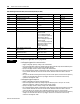
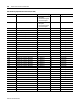
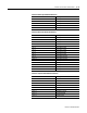
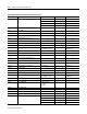
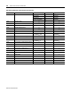
Table B.30 Diagnostic Data Table (Self-test Results) Read (File N30)
Parameter No. Parameter Name Master Module Range Element Range
NOTE
Notes for PC application or PLC programmer
Oscillograph triggered via a communication:
• Trigger oscillograph capture by writing to the command table.
• Check oscillograph data readiness by reading diagnostic table (should be ready almost immediately since
maximum pre-trigger is used for comm port oscillograph requests).
• Specify oscillograph channel to read by writing to the command table.
• Get oscillograph data by reading oscillograph data table. Subsequent reads return remaining sets of data
for that channel. After the last set of data for that channel, additional reads return data for the next
channel.
• Once you have finished collecting all of the data you desire for that capture, release hold of the capture by
writing to the command table. This allows pre-trigger collection of new data and clears the ready
indication in the diagnostic table.
Oscillograph trigger via setpoint:
• Trigger oscillograph with a properly configured setpoint.
• Check oscillograph data readiness by reading diagnostic table (may have to wait up to 1.2 seconds;
depends on sample rate, number of captures and pre-trigger settings).
• Specify oscillograph channel to read by writing to the command table.
• Get oscillograph data by reading oscillograph data table. Subsequent reads return remaining sets of data
for that channel. After the last set of data for that channel, additional reads return data for the next
channel. All data for all 7 channels can be retrieved by performing a series of successive reads.
• Once you have finished collecting all of the data you desire for that capture, release hold of the capture by
writing to the command table. This allows pre-trigger collection of new data and clears the ready
indication in the diagnostic table.