
Installation Instructions Owner's manual

Publication 1403-IN005A-EN-P
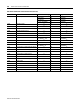
Ethernet Communication Card Data Tables B-37
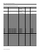
Waveform Capture Data Equation
For PT Secondary Values < 138 Max Voltage = 138.0
For PT Secondary Values
≥ 138 Max Voltage = 399.0
For xM01A or xM01B Max Current = 1.42 (1403-MM or 1403-LM)
For xM05A or xM05B Max Current = 7.10
Max Counts = 4095
Max Voltage or Max Current 2×()
Max Counts
PT or CT Primary
PT or CT Secondary
Oscillogram Data Point× Voltage or Current=×
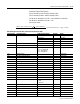
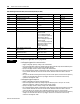
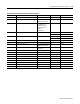
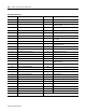
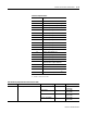
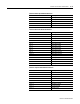
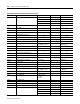
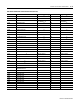
Table B.30 Diagnostic Data Table (Self-test Results) Read (File N30)
Parameter No. Parameter Name Master Module Range Element Range
20.1 Time Stamp of Diagnostic Data Year 1 16-bit Integer
Month, Date 2 8-bit, 8-bit
Hour, Minute 3 8-bit, 8-bit
Seconds, Hundredths 4 8-bit, 8-bit
20.2 Bulletin Number 1403 5 1403
20.3 Master Module FRN 0 to +32767 6 0 to +32767
20.4 Options Bit Field Bit 0 - High Voltage (A)
Bit 1 - Low Voltage (B)
Bit 2 - 1 Amp Device
Bit 3 - 5 Amp Device
7 16-bit Integer
20.5 Summary Status 8 16-bit Integer
20.6 Master Module ROM Status 9 16-bit Integer
20.7 Master Module RAM Status 10 16-bit Integer
20.8 NV RAM Status 11 16-bit Integer
20.9 Power Supply Check 12 16-bit Integer
20.10 Data Acquisition 13 16-bit Integer
20.11 Master Module Watchdog Timer 14 16-bit Integer
20.12 Real Time Clock Status 15 16-bit Integer
20.13 Reserved 16
20.14 Reserved 17
20.15 Battery Usage 0 to 32767 18 0 to 32767
20.16 Smart Communication Card Status 19 16-bit Integer
20.17 Reserved 20
20.18 Smart Communication Card Type 0 = none
1 = RIO
2 = Ethernet
21 0 to 32767
20.19 Smart Communication Card FRN 0 to 32767 22 0 to 32767
20.20 Number of Display Modules 0 to 3 23 0 to 3
20.21 Display Module Status 24 16-bit Integer
20.22 Display Module Self Test Results Word 1 25 16-bit Integer
20.23 Display Module Self Test Results Word 2 26 16-bit Integer
20.24 Display Module No. 1 FRN 0 to 32767 27 0 to 32767