
Installation Instructions Owner's manual

Publication 1403-IN005A-EN-P
Ethernet Communication Card Data Tables B-15
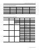
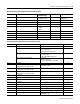
9.21 L3-N Voltage
0 to 9999x10
21
volts
24
0 to 9999x10
21
9.22 3-Phase Average Voltage (L-N)
0 to 9999x10
21
volts
25
0 to 9999x10
21
9.23 Reserved 26
9.24 Last Cycle Frequency 20.0 to 132.0 27 20.0 to 132.0
9.25 Phase Rotation 0 = No Rotation
1 = ABC
2 = ACB
28 0 to 2
9.26 Number of Snapshot Logs Requested 1 to 50 29 1 to 50
9.27 No. of Snapshot Log Received (Counter) 1 to 50 30 1 to 50
9.28 Number of Snapshot Log Being Returned 1 to 50 31 1 to 50
9.29 Internal Identifier -32767 to +32767 32 -32767 to +32767
(1) ID=54 for log selection command.
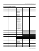
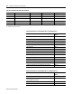
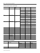
Table B.13 Snapshot 46 Parameter Record Table Read (File F19)
(1)
Parameter No. Parameter Name Master Module
Parameter Range
Element Range
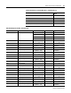
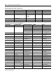
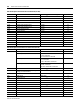
Table B.14 Snapshot 16 Parameter Record Table Read (File F19)
Parameter No. Parameter Name Master Module Parameter Range Element
9a.1 Timestamp; Year 1998 to 2097 1
Timestamp; Month, Date 257 to 3103
Month = Value/256
Date = Remainder of Value/256
2
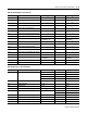
Timestamp; Hour, Minute 0 to 5947
Hour = Value/256
Minute = Remainder of Value/256
3
Timestamp; Seconds, Hundreths 0 to 15203
Seconds = Value/256
hSeconds = Remainder of Value/256
4
9a.2 Reserved 0 5
9a.3 L1-L2 Voltage (in Delta modes) or
L1-N Voltage (in non-Delta modes)
0 to 9999x10
21
Volts
6
9a.4 L2-L3 Voltage (in Delta modes) or
L2-N Voltage (in non-Delta modes)
0 to 9999x10
21
Volts
7
9a.5 L3-L1 Voltage (in Delta modes) or
L3-N Voltage (in non-Delta modes)
0 to 9999x10
21
Volts
8
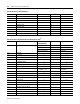
9a.6 L1 Current
0 to 9999x10
21
Amps
9
9a.7 L2 Current
0 to 9999x10
21
Amps
10
9a.8 L3 Current
0 to 9999x10
21
Amps
11
9a.9 L4 Current
0 to 9999x10
21
Amps
12
9a.10 Voltage Unbalance 0 to 100% 13
9a.11 Current Unbalance 0 to 100% 14
9a.12 Total Real Power
0 to 9999x10
21
kW
15
9a.13 Total Reactive Power
0 to 9999x10
21
kVAR
16
9a.14 Demand kW
0 to 9999x10
21
kW
17