
Installation Instructions Owner's manual

Publication 1403-IN005A-EN-P
Ethernet Communication Card Data Tables B-9
Reserved b4 = not used
Set Time (DV6) b5 = 1
Relay 1 (DV7) b6 = 1
Relay 2 (DV8) b7 = 1
Select Setpoint Number (DV9) b8 = 1
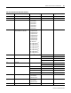
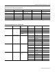
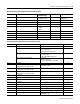
Table B.7 Bit Fields for Command Data Table - (Command Word 2)
Command Bit Location and
Value
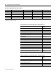
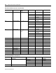
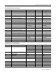
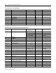
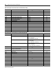
Table B.8 Voltage/Current Data - Read (File F14)
Parameter No. Parameter Name Master Module Range Element Range
4.1 Time Stamp Year 1 32-bit Float
Month, Date 2 32-bit Float
Hour, Minute 3 32-bit Float
Seconds, Hundredths 4 32-bit Float
4.2 L1 Current
0 to 9999x10
21
amps
5
0 to 9999x10
21
4.3 L2 Current
0 to 9999x10
21
amps
6
0 to 9999x10
21
4.4 L3 Current
0 to 9999x10
21
amps
7
0 to 9999x10
21
4.5 L4 (Neutral) Current
0 to 9999x10
21
amps
8
0 to 9999x10
21
4.6 3-Phase Average Current
0 to 9999x10
21
amps
9
0 to 9999x10
21
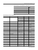
4.7 Positive Sequence Current
0 to 9999x10
21
amps
10
0 to 9999x10
21
4.8 Negative Sequence Current
0 to 9999x10
21
amps
11
0 to 9999x10
21
4.9 Percent Current Unbalance 0.0 to 100.0 12 0.0 to 100.0
4.10 L1 to L2 Voltage
0 to 9999x10
21
amps
13
0 to 9999x10
21
4.11 L2 to L3 Voltage
0 to 9999x10
21
volts
14
0 to 9999x10
21
4.12 L3 to L1 Voltage
0 to 9999x10
21
amps
15
0 to 9999x10
21
4.13 AUX Voltage
0 to 9999x10
21
volts
16
0 to 9999x10
21
4.14 3-Phase Average Voltage (L-L)
0 to 9999x10
21
amps
17
0 to 9999x10
21
4.15 Positive Sequence Voltage
0 to 9999x10
21
volts
18
0 to 9999x10
21
4.16 Negative Sequence Voltage
0 to 9999x10
21
volts
19
0 to 9999x10
21
4.17 Percent Voltage Unbalance 0.0 to 100.0 20 0.0 to 100.0
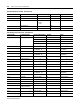
4.18 L1-N Voltage
0 to 9999x10
21
volts
21
0 to 9999x10
21
4.19 L2-N Voltage
0 to 9999x10
21
volts
22
0 to 9999x10
21
4.20 L3-N Voltage
0 to 9999x10
21
volts
23
0 to 9999x10
21
4.21 3-Phase Average Voltage (L-N)
0 to 9999x10
21
volts
24
0 to 9999x10
21