
Installation Instructions Owner's manual

Publication 1403-IN005A-EN-P
B-8 Ethernet Communication Card Data Tables
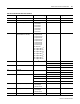
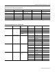
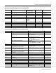
3.12 Present Unit Password 0 to 9999 18 0 to 9999
Reserved 19
Reserved 20
Reserved 21
Reserved 22
(1) See Table B.6 o n pageB-8 for specific command bits to enable these features.
(2) Available on firmware V3.00 or later.
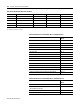
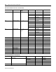
Table B.5 Command Data Table Write (File N13)
Parameter No. Parameter Name Master Module Range Element Range
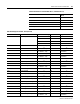
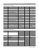
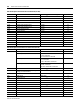
Table B.6 Bit Fields for Command Data Table -(Command Word 1)
Command Bit Location and
Value
Clear Snapshot Log b0 = 1
Clear Min_Max Log b1 = 1
Restore Factory Default Configuration b2 = 1
Clear Hold of Oscillograph Capture #1 (Reserved on 1403-LM) b3 = 1
Initiate Oscillograph Capture #1 (Reserved on 1403-LM) b4 = 1
Force Self Test b5 = 1
Clear Status Input Counter 1 b6 = 1
Clear Status Input Counter 2 b7 = 1
Clear Status Input Counter 3 b8 = 1
Clear Status Input Counter 4 b9 = 1
Clear Battery Usage Timer b10 = 1
Reserved b11 = 1
Synchronize Demand Interval b12 = 1
Clear Hold of Oscillograph Capture #2 (Reserved on 1403-LM) b13 = 1
Initiate Oscillograph Capture #2 (Reserved on 1403-LM) b14 = 1
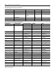
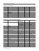
Table B.7 Bit Fields for Command Data Table - (Command Word 2)
Command Bit Location and
Value
Set Analysis Channel Request (DV1) b0 = 1
Set Oscillogram Channel Request (DV2)
(Not Available on 1403-LM)
b1 = 1
Set W Hours (DV3) b2 = 1
Set VAR Hours (DV4) b3 = 1