
Installation Instructions Owner's manual

Publication 1403-IN005A-EN-P
Ethernet Communication Card Data Tables B-7
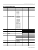
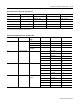
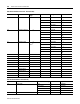
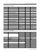
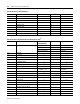
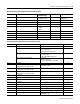
Table B.5 Command Data Table Write (File N13)
Parameter No. Parameter Name Master Module Range Element Range
3.1 Command Word 1 (Bit Fields) SeeTable B.6 1 0 to 32,767
3.2 Command Word 2 (Bit Fields) SeeTable B.7 2 0 to 511
3.3
Harmonic Analysis
(1)
1 = L1 Voltage
2 = L1 Current
3 = L2 Voltage
4 = L2 Current
5 = L3 Voltage
6 = L3 Current
7 = L4 Current
31 to 7
3.4 Oscillograph Channel Request
(Not Available on 1403-LM)
1 = Capture #1 V1
2 = Capture #1 I1
3 = Capture #1 V2
4 = Capture #1 I2
5 = Capture #1 V3
6 = Capture #1 I3
7 = Capture #1 I4
8 = Ch-A 12 Cycle
9 = Ch-B 12 Cycle
10 = Reserved
11 = Capture #2 V1
(2)
12 = Capture #2 I1
(2)
13 = Capture #2 V2
(2)
14 = Capture #2 I2
(2)
15 = Capture #2 V3
(2)
16 = Capture #2 I3
(2)
17 = Capture #2 I4
(2)
4 1 to 17
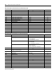
3.5 W Hour Data for Set Command
-9999x10
8
to +9999x10
8
5 -9999 to 9999
6
±0 to 8
3.6 VAR Hour Data for Set Command
-9999x10
8
to +9999x10
8
7 -9999 to 9999
8
±0 to 8
3.7 Reserved 9
10
3.8 Time for Set Command Year 11 1998 to 2097
Month, Day 12 8-bit, 8-bit
Hour, Minutes 13 8-bit, 8-bit
Seconds, Hundredths 14 8-bit, 8-bit
3.9 Force Specifics Relay 1 1 = Energize
2 = De-energize
4 = Remove Force
15 1, 2, 4
3.10 Force Specifics Relay 2 1 = Energize
2 = De-energize
4 = Remove Force
16 1, 2, 4
3.11 Setpoint Number 1 to 20 17 1 to 20