
Installation Instructions Owner's manual


Publication 1403-IN005A-EN-P
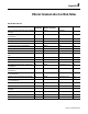
Ethernet Communication Card Data Tables B-3
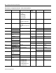
1.15 Snapshot Interval -
Hours
0 19 0 to 32,767
1.16 Snapshot Interval -
Minutes
0 20 0 to 32,767
1.17 Snapshot Interval -
Seconds
0 21 0 to 32,767
1.18 Snapshot Buffer Type 0 = Fill and Stop
1 = Circular
122 0 to 1
1.19
Snapshot Param #1
(3)
See Table B.3 62 23 0 to 64
1.20
Snapshot Param #2
(3)
See Table B.3 63 24 0 to 64
1.21
Snapshot Param #3
(3)
See Table B.3 47 25 0 to 64
1.22
Oscillograph Type
(3)
0 = V2.10 or earlier
compatible mode
1 = 10.8 kHz, 1 capture
2 = 10.8 kHz, 2 captures
3 = 5.4 kHz, 1 capture
4 = 5.4 kHz, 2 captures
5 = 2.7 kHz, 1 capture
6 = 2.7 kHz, 2 captures
026 0 to 6
1.23 Oscillograph
Overwrite Timeout
(3)
1 to 4320 minutes 1 27 1 to 4320
1.24 Output Pulse Relay
No.
0 = None
1 = Relay 1
2 = Relay 2
028 0 to 2
1.25 Output Pulse
Parameter
0 = kWh Forward
1 = kWh Reverse
2 = kVarh Forward
3 = kVarh Reverse
029 0 to 3
1.26 Output Pulse
Increment
1 to 32766 1 30 1 to 32766
1.27 Output Pulse Width
(ms)
(4)
0, 40 to 2000 100 31 40 to 2000
1.28 Ch A 12 Cycle
Oscillogram
(5)
1 = Phase 1 Voltage
2 = Phase 1 Current
3 = Phase 2 Voltage
4 = Phase 2 Current
5 = Phase 3 Voltage
6 = Phase 3 Current
7 = Phase 4 Current
132 1 to 7
1.29 Ch B 12 Cycle
Oscillogram
(5)
1 = Phase 1 Voltage
2 = Phase 1 Current
3 = Phase 2 Voltage
4 = Phase 2 Current
5 = Phase 3 Voltage
6 = Phase 3 Current
7 = Phase 4 Current
233 1 to 7
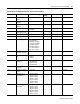
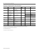
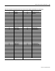
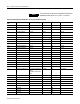
Table B.2 Device Configuration Data Table - Write and Read (File N11)
Parameter No. Parameter Name Master Module Range Default
Setting
Element Range