
Installation Instructions Owner's manual
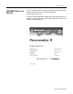


Publication 1403-IN005A-EN-P
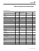
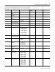
B-2 Ethernet Communication Card Data Tables
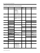
Table B.2 Device Configuration Data Table - Write and Read (File N11)
Parameter No. Parameter Name Master Module Range Default
Setting
Element Range
1.1 Voltage Mode 0 = Demo
1 = Single
2 = Open Delta
3 = 3-Wire Delta
4 = 4-Wire Wye
5 = Direct Delta
(1)
41 0 to 5
1.2 Present Unit Password -1 is always returned on a
Read
0 to 9999 is required for a
Write
0 2 -1 to +9999
1.3 New Password -1 does not change the
password
0 to 9999 is new password
value
0 3 -1 to +9999
1.4 Voltage Scale 1.0 to 10,000,000.0 120.0 4 0 to 9999
PT Primary 5 0 to 4
1.5 Voltage Scale 1 to 999 120 6 1 to 999
PT Secondary
1.6 Current Scale (For I1,
I2, I3)
1.0 to 10,000,000.0
1 or 5
(2)
7 0 to 9999
CT Primary 8 0 to 4
1.7 Current Scale (For I1,
I2, I3)
1 to 999
1 or 5
(2)
9 1 to 999
CT Secondary
1.8 Analog Input Scale 1.0 to 10,000,000.0 1.0 10 0 to 9999
PT Primary 11 0 to 4
1.9 Analog Input Scale 1 to 999 1 12 1 to 999
PT Secondary
1.10 Neutral Current Scale
(For I4)
1.0 to 10,000,000.0
1 or 5
(2)
13 0 to 9999
CT Primary 14 0 to 4
1.11 Neutral Current Scale
(For I4)
1 to 999
1 or 5
(2)
15 1 to 999
CT Secondary
1.12 Demand Period Length -99 to +99 1 16 -99 to +99
1.13 Number of Demand
Periods
1 to 15 1 17 1 to 15
1.14
Snapshot Log Type
(3)
0 = 46 param record
1 = 16 param record
2 = 8 param record
3 = 4 param record
4 = 3 and 7 param record
5 = 1 param record
018 0 to 5