
Installation Instructions Owner's manual

Publication 1403-IN005A-EN-P
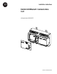
6 Product Description
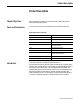
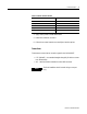
Indicators
Four LED indicators provide information about the operating status of the
card.
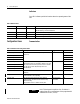
Configuration Items
Communication
Table 3 LED Indicators
Label Name LED Color LED State and Communications Condition
RDY Ready Red ON = Control power applied
ON/OFF Flashing = Self-test initialization
LK Link Green ON = UTP (10BaseT) cable properly connected
RX Receive Green ON/OFF Flashing = Receiving Data
TX Transmit Green ON/OFF Flashing = Transmitting Data
Table 4 Communication Configuration Items
Communication Parameter Description Range Default
IP Address Byte a IP address of this Powermonitor. (Normally in the form
128.1.1.1)
0 to 255 128
IP Address Byte b 1
IP Address Byte c 1
IP Address Byte d Device ID#
Subnet Mask Byte a Specifies the subnet mask to apply to the IP address.
Network ID and Host are specified by address class. Zero
bits in the mask indicate bit positions of the host number;
one bits are for subnet ID. (Normally in the form
255.255.255.0)
0 to 255 255
Subnet Mask Byte b 255
Subnet Mask Byte c 255
Subnet Mask Byte d 0
Physical Ethernet Port Selects the Ethernet media (0=UTP/10BaseT, 1=AUI/
10Base5)
0 = UTP, 1 =AUI 0 = UTP
Keep Alive Time The maximum allowable time any socket is dedicated to a
connection that is not responding.
5 to 3600 seconds 30
Inactivity Time The maximum allowable time the entire Ethernet
communication card waits with no network activity
before rebooting.
Set parameter to zero to disable inactivity time.
0 to 1440 minutes
0 = Disabled
30
NOTE
BOOTP, the dynamic acquisition of an IP address, is
enabled when all four address bytes of the programmed IP
address are set to zero. (0.0.0.0)