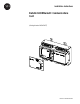
Installation Instructions Bulletin 1403 Ethernet® Communications Card (Catalog Number 1403-NENET) 1 Publication 1403-IN005A-EN-P
Bulletin 1403 Ethernet® Communications Card Important User Information Because of the variety of uses for the products described in this publication, those responsible for the application and use of this control equipment must satisfy themselves that all necessary steps have been taken to assure that each application and use meets all performance and safety requirements, including any applicable laws, regulations, codes and standards.
Table of Contents Product Description Chapter Objectives . . . . . . . . . . . . . . . . . . . . . . . . . . . . . . . . . . . . . . . 1 Terms and Conventions . . . . . . . . . . . . . . . . . . . . . . . . . . . . . . . . . . . 1 Abbreviations and Terms . . . . . . . . . . . . . . . . . . . . . . . . . . . . . . . . . . 1 Introduction . . . . . . . . . . . . . . . . . . . . . . . . . . . . . . . . . . . . . . . . . . . . 1 Features . . . . . . . . . . . . . . . . . . . . . . . . . . . . . . . . . . . . .
Table of Contents ii Odd Harmonic Distortion Table Channels 1 to 7 Read (File F24) . . . . . . . . . . . . . . . . . . . . . . . . . . B-26 Even Harmonic Magnitude Data Table Channel 1 to 7 Read (File F25) . . . . . . . . . . . . . . . . . . . . . . . . . . B-28 Odd Harmonic Magnitude Data Table (File F26) . . . . . . . . . . . . B-29 Even Harmonic Phase Angle Data Table Channels 1 to 7 Read (File F27) . . . . . . . . . . . . . . . . . . . . . . . . . .
Product Description Product Description Chapter Objectives After completing this chapter, you should be able to identify the product features and system applications.
2 Product Description Features The Ethernet Communication Card features include: • • • • • • • • Connect to Allen-Bradley PLC-5 ® Ethernet processors Connect to Allen-Bradley SLC 5/05 ™ Ethernet processor Built-in internet web page support Compatible with RSEnergy™, RSView32™ and RSPower32™ software Ethernet communication rate: 10Mbps Compatible with commercially available network bridges and routers Fully software configurable Supports RSLinx™ and WINtelligent Linx™ (emulates SLC 500™) Figure 1 Catalo
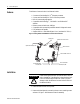
Product Description 3 Figure 2 Blank Plate Removal 3. If you plan to remove the communications card at a later date, retain the blank plate. Otherwise, dispose of properly. 4. Remove the communications card from the static protection shipping bag. 5. Grasp the card with the components side up and the four LEDs on the bottom. Place the right index finger in the top notch and the thumb in the bottom notch. 6.
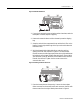
4 Product Description IMPORTANT Make sure cables do not twist. Figure 4 Installing Closure Plate NOTE Refer to Appendix D on page D-1, for screw torque requirements and wire sizes. 8. Apply Master Module control power. Field Service Considerations If the Ethernet Communications Card requires service, please contact your nearest Rockwell Automation Sales Office. To minimize your inconvenience, the initial installation should be performed in a manner which makes removal easy.
Product Description 5 Table 2 Communication Parameters Parameter Value Baud Rate 38,400 Parity None Data Bits 8 Stop Bits 1 Flow Control None 4. Apply control power to the Master Module. 5. Press Enter (or Return) on the PC. 6. Follow the on-screen instructions to modify and save the options. Connections There are two communication connection types for the 1403-NENET. • UTP (10BaseT) - use a standard straight through RJ45 cable to connect to an Ethernet hub.
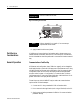
6 Product Description Indicators Four LED indicators provide information about the operating status of the card.
Product Description 1403-NENET Web Access Overview 7 The HTTP (Web) interface is accessed from a web browser by entering the IP address of the Powermonitor II in the address combo box (example: http://128.1.1.151). A menu of all the available tables is presented with each table name shown as a hyperlink. Clicking on the link brings up a tabular display of the values in that table and the value descriptions.
8 Product Description Publication 1403-IN005A-EN-P
Appendix A Catalog Number Explanation Communications Cards 1403 - NENET Bulletin Number 1403 = Powermonitor II Family of products. 1 Type of Device NENET = Plug-in Communication Card for Bulletin 1403-MM and 1403-LM Devices (TCP/IP Ethernet).
A-2 Catalog Number Explanation Publication 1403-IN005A-EN-P
Appendix B Ethernet Communication Card Data Tables Table B.
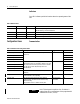
B-2 Ethernet Communication Card Data Tables Table B.2 Device Configuration Data Table - Write and Read (File N11) Parameter No. Parameter Name Master Module Range Default Setting Element Range 1.1 Voltage Mode 0 = Demo 1 = Single 2 = Open Delta 3 = 3-Wire Delta 4 = 4-Wire Wye 5 = Direct Delta(1) 4 1 0 to 5 1.2 Present Unit Password -1 is always returned on a Read 0 to 9999 is required for a Write 0 2 -1 to +9999 1.
Ethernet Communication Card Data Tables B-3 Table B.2 Device Configuration Data Table - Write and Read (File N11) Parameter No. Parameter Name 1.15 Master Module Range Default Setting Element Range Snapshot Interval Hours 0 19 0 to 32,767 1.16 Snapshot Interval Minutes 0 20 0 to 32,767 1.17 Snapshot Interval Seconds 0 21 0 to 32,767 1.18 Snapshot Buffer Type 0 = Fill and Stop 1 = Circular 1 22 0 to 1 1.19 Snapshot Param #1(3) See Table B.3 62 23 0 to 64 1.
B-4 Ethernet Communication Card Data Tables Table B.2 Device Configuration Data Table - Write and Read (File N11) Parameter No. Parameter Name Master Module Range Default Setting Element Range 1.30 Oscillograph Buffer Type(5) 0 = Hold 1 = Overwrite 1 34 0 to 1 1.31 Number of Pretrigger -1 = No Pretrig Cycles for the 12 Cycle 0 to +8 = Cycles Oscillogram(5) 0 35 -1 to +8 1.32 IEEE 519 Max. Short Circuit Current(5) 0.0 to 10,000,000.0 0 36 0 to 9999 37 0 to 4 IEEE 519 Max.
Ethernet Communication Card Data Tables B-5 Table B.3 Configurable Snapshot Parameter List (selection list for Table B.2, parameters 1.19, 1.20 and 1.
B-6 Ethernet Communication Card Data Tables NOTE The device does not respond to a broadcast of this table. IP addresses are stored as a.b.c.d (e.g. 128.1.1.1; a=128). Table B.4 Communications Configuration Table - Write and Read (File N12) Parameter No. Parameter Name Master Module Range Default Element Range 2.1 IP Address Byte a 0 to 255 128 1 0 to 255 2.2 IP Address Byte b 0 to 255 1 2 0 to 255 2.3 IP Address Byte c 0 to 255 1 3 0 to 255 2.
Ethernet Communication Card Data Tables B-7 Table B.5 Command Data Table Write (File N13) Parameter No. Parameter Name Master Module Range Element Range 3.1 Command Word 1 (Bit Fields) See Table B.6 1 0 to 32,767 3.2 Command Word 2 (Bit Fields) See Table B.7 2 0 to 511 3.3 Harmonic Analysis(1) 1 = L1 Voltage 2 = L1 Current 3 = L2 Voltage 4 = L2 Current 5 = L3 Voltage 6 = L3 Current 7 = L4 Current 3 1 to 7 3.
B-8 Ethernet Communication Card Data Tables Table B.5 Command Data Table Write (File N13) Parameter No. Parameter Name Master Module Range Element Range 3.12 Present Unit Password 0 to 9999 18 0 to 9999 Reserved 19 Reserved 20 Reserved 21 Reserved 22 (1) See Table B.6 o n pageB-8 for specific command bits to enable these features. (2) Available on firmware V3.00 or later. Table B.
Ethernet Communication Card Data Tables B-9 Table B.7 Bit Fields for Command Data Table - (Command Word 2) Command Bit Location and Value Reserved b4 = not used Set Time (DV6) b5 = 1 Relay 1 (DV7) b6 = 1 Relay 2 (DV8) b7 = 1 Select Setpoint Number (DV9) b8 = 1 Table B.8 Voltage/Current Data - Read (File F14) Parameter No. Parameter Name Master Module Range Element Range 4.
B-10 Ethernet Communication Card Data Tables Table B.8 Voltage/Current Data - Read (File F14) Parameter No. Parameter Name Master Module Range Element Range 4.22 Reserved Word 4.23 Last Cycle Frequency 20.0 to 132.0 26 0 to 9999 4.24 Phase Rotation 0 = No Rotation 1 = ABC 2 = ACB 27 0 to 2 25 Reserved Word 28 Reserved Word 29 Table B.9 Real-Time Power Data - Read (File F15) Parameter No. Parameter Name Master Module Range Element Range 5.
Ethernet Communication Card Data Tables B-11 Table B.9 Real-Time Power Data - Read (File F15) Parameter No. Parameter Name Master Module Range Element Range 5.22 (1) L1 Distortion PF -100.0 to +100.0 25 -100.0 to +100.0 5.23 L2 Distortion PF(1) -100.0 to +100.0 26 -100.0 to +100.0 5.24 L3 Distortion PF(1) -100.0 to +100.0 27 -100.0 to +100.0 5.25 Total Distortion PF(1) -100.0 to +100.0 28 -100.0 to +100.
B-12 Ethernet Communication Card Data Tables Table B.10 Cumulative Power Data - Read (File N16) Parameter No. Parameter Name 6.5 kVAR Hours Forward 0 to 1.0x10¹² 6.6 6.7 Master Module Range kVAR Hours Reverse -1.0x10¹² to 0 kVAR Hours Net -1.0x10¹² to 1.
Ethernet Communication Card Data Tables B-13 Table B.11 Demand Data - Read (File F17) Parameter No. Parameter Name Master Module Range Element Range 7.3 Demand Power 0 to 9999x1021 W 6 0 to 9999x1021 7.4 Demand Reactive Power 0 to 9999x1021 VAR 7 0 to 9999x1021 7.5 Demand Apparent Power 0 to 9999x1021 VA 8 0 to 9999x1021 7.6 Projected No. 1 Demand Current 0 to 9999x1021 amps 9 0 to 9999x1021 7.7 Projected No. 1 Demand Power 0 to 9999x1021 W 10 0 to 9999x1021 7.
B-14 Ethernet Communication Card Data Tables Table B.12 Event Log - Read (File N18)(1) Parameter No. Parameter Name Master Module Range Element Range 8.11 Number of Event Log Being Returned 1 to 100 15 1 to 100 8.12 Internal Identifier -32767 to +32767 16 -32767 to +32767 Reserved Word 17 Reserved Word 18 Reserved Word 19 Reserved Word 20 Reserved Word 21 Reserved Word 22 Reserved Word 23 (1) ID=23 for log selection command. Table B.
Ethernet Communication Card Data Tables B-15 Table B.13 Snapshot 46 Parameter Record Table Read (File F19)(1) Parameter No. Parameter Name Master Module Parameter Range Element Range 9.21 L3-N Voltage 0 to 9999x1021 volts 24 0 to 9999x1021 9.22 3-Phase Average Voltage (L-N) 0 to 9999x1021 volts 25 0 to 9999x1021 9.23 9.24 9.25 Reserved Last Cycle Frequency Phase Rotation 26 27 28 20.0 to 132.0 0 to 2 9.26 9.27 9.28 9.29 Number of Snapshot Logs Requested No.
B-16 Ethernet Communication Card Data Tables Table B.14 Snapshot 16 Parameter Record Table Read (File F19) Parameter No. 9a.15 Parameter Name Demand kVAR Master Module Parameter Range 9a.16 9a.17 Total True PF kWh net -100 to +100 9a.18 kVARh net 21 9a.19 9a.20 9a.21 9a.22 9a.23 9a.24 Number of Records Requested Number of Records Read so far Record Number Returned Internal Identifier Reserved Reserved -9999x1021 to +9999x1021 kVARh 1 to 265 1 to 265 1 to 265 0 to 255 0 0 9a.25 9a.
Ethernet Communication Card Data Tables B-17 Table B.15 Snapshot 8 Parameter Record Table Read (File F19) Parameter No. 9b.15 9b.16 9b.17 9b.18 9b.19 9b.20 9b.21 Parameter Name Reserved Reserved Reserved Reserved Reserved Reserved Reserved Master Module Parameter Range 0 0 0 0 0 0 0 9b.22 9b.23 9b.24 9b.25 9b.26 9b.27 9b.28 9b.29 Reserved Reserved Reserved Reserved Reserved Reserved Reserved Reserved 0 0 0 0 0 0 0 0 Element 18 19 20 21 22 23 24 25 26 27 28 29 30 31 32 Table B.
B-18 Ethernet Communication Card Data Tables Table B.16 Snapshot 4 Parameter Record Table Read (File F19) Parameter No. 9c.16 9c.17 9c.18 9c.19 9c.20 9c.21 9c.22 Parameter Name Reserved Reserved Reserved Reserved Reserved Reserved Reserved Master Module Parameter Range 0 0 0 0 0 0 0 9c.23 9c.24 9c.25 9c.26 9c.27 9c.28 9c.29 Reserved Reserved Reserved Reserved Reserved Reserved Reserved 0 0 0 0 0 0 0 Element 19 20 21 22 23 24 25 26 27 28 29 30 31 32 Table B.
Ethernet Communication Card Data Tables B-19 Table B.17 Snapshot 3 and 7 Parameter Record Table Read (File F19) Parameter No. 9d.14 9d.15 9d.16 9d.17 9d.18 9d.19 9d.20 Parameter Name Number of Records Read so far Record Number Returned Internal Identifier Reserved Reserved Reserved Reserved Master Module Parameter Range 1 to 845 1 to 845 0 to 255 0 0 0 0 9d.21 9d.22 9d.23 9d.24 9d.25 9d.26 9d.27 9d.28 9d.
B-20 Ethernet Communication Card Data Tables Table B.18 Snapshot 1 Parameter Record Table Read (File F19) Parameter No. 9e.15 9e.16 9e.17 9e.18 9e.19 9e.20 9e.21 Parameter Name Reserved Reserved Reserved Reserved Reserved Reserved Reserved Master Module Parameter Range 0 0 0 0 0 0 0 9e.22 9e.23 9e.24 9e.25 9e.26 9e.27 9e.28 9e.29 Reserved Reserved Reserved Reserved Reserved Reserved Reserved Reserved 0 0 0 0 0 0 0 0 Element 18 19 20 21 22 23 24 25 26 27 28 29 30 31 32 Table B.
Ethernet Communication Card Data Tables B-21 Table B.19 Power Snapshot Log Data Table (File F20)(1) Parameter No. Parameter Name 10.17 10.18 10.19 10.20 10.21 10.22 10.23 10.24 10.25 10.26 10.27 10.
B-22 Ethernet Communication Card Data Tables Table B.20 Min_Max Log - Read (File N21)(1) Parameter No. Parameter Name 11.1 Time Stamp of last Min/Max Log Reset 11.2 Time Stamp of MIN for Parameter 11.3 MIN Value for Parameter Master Module Parameter Range Year Month, Date Hour, Minute Seconds, Hundredths Year Month, Date Hour, Minute Seconds, Hundredths 0 to 9999x1021 11.4 Time Stamp of MAX for Parameter Year Month, Date Hour, Minute Seconds, Hundredths 11.
Ethernet Communication Card Data Tables B-23 Table B.21 Log Selection Command Table Write (File N22) Param. No. Parameter Name Master Module Range Element 12.1 Selected Log 1 23 = Event Log 24 = Min/Max Log 54 = Snapshot V/I Log, or 16, 8, 3 and 7, 1 parameter records 59 = Snapshot Power Log 23, 24, 54, 59 12.
B-24 Ethernet Communication Card Data Tables Table B.22 Available Min/Max Log Parameters (Identifiers for parameter 12.
Ethernet Communication Card Data Tables B-25 Harmonic Distortion Tables - Read Harmonic Distortion Data Tables for Channel 1 through Channel 7 are identical. There are a total of 14 tables for this information. (V1, V2, V3, I1, I2, I3, I4) The table sizes indicate this is Harmonic Distortion Data. The Channel Number designates which one. Table B.23 Even Harmonic Distortion Table - Channel 1 to 7 Read (File F23) Parameter No. 13.1 13.
B-26 Ethernet Communication Card Data Tables Table B.23 Even Harmonic Distortion Table - Channel 1 to 7 Read (File F23) Parameter No. 13.19 13.20 13.21 13.22 13.23 13.24 13.25 13.26 13.27 13.28 13.
Ethernet Communication Card Data Tables B-27 Table B.24 Odd Harmonic Distortion Table - Channels 1 to 7 Read (File F24) Parameter No. 14.9 14.10 14.11 14.12 14.13 14.14 14.15 14.16 14.17 14.18 14.19 14.20 14.21 14.22 14.23 14.24 14.25 14.26 14.27 14.28 14.
B-28 Ethernet Communication Card Data Tables Harmonic Magnitude Data Tables for Channel 1 through Channel 7 are identical. There are a total of 14 tables for this information. (V1, V2, V3, I1, I2, I3, I4). Table B.25 Even Harmonic Magnitude Data Table Channel 1 to 7 Read (File F25) Parameter No. 15.1 15.2 15.
Ethernet Communication Card Data Tables B-29 Table B.25 Even Harmonic Magnitude Data Table Channel 1 to 7 Read (File F25) Parameter No. 15.21 Parameter Name Harmonic Magnitude - Twenty-sixth (Not Available on 1403-LM) 15.22 Harmonic Magnitude - Twenty-eighth (Not Available on 1403-LM) 15.
B-30 Ethernet Communication Card Data Tables Table B.26 Odd Harmonic Magnitude Data Table (File F26) Parameter No. 16.11 Parameter Name Harmonic Magnitude - Seventh (Not Available on 1403-LM) 16.12 16.
Ethernet Communication Card Data Tables B-31 Harmonic Phase Angle Data Tables for Channel 1 through Channel 7 are identical. There are a total of 14 tables for this information. (V1, V2, V3, I1, I2, I3, I4) Table B.27 Even Harmonic Phase Angle Data Table Channels 1 to 7 Read (File F27) Parameter No. 17.1 17.2 17.3 Parameter Name Reserved Word Reserved Word Reserved Word 17.4 17.5 17.6 17.7 Reserved Word Reserved Word Reserved Word Channel Number (Not Available on 1403-LM) 17.
B-32 Ethernet Communication Card Data Tables Table B.27 Even Harmonic Phase Angle Data Table Channels 1 to 7 Read (File F27) Parameter No. 17.22 17.23 17.24 17.25 17.26 17.27 17.28 17.
Ethernet Communication Card Data Tables B-33 Table B.28 Odd Harmonic Phase Angle Data Table (File F28) Parameter No. 18.15 18.16 18.17 18.18 18.19 18.20 18.21 18.22 18.23 18.24 18.25 18.26 18.27 18.28 18.
B-34 Ethernet Communication Card Data Tables Table B.29 Waveform Capture Data - Read (File N29) Parameter No. 19.1 Parameter Name Time Stamp of Oscillogram (Not Available on 1403-LM) 19.2 Channel Number (Not Available on 1403-LM) 19.3 Channel Data Count (Not Available on 1403-LM) Oscillogram Chronological Reference Number (Not Available on 1403-LM) Oscillogram Block Number (Not Available on 1403-LM) Actual Channel Number (Not Available on 1403-LM) 19.4 19.5 19.
Ethernet Communication Card Data Tables B-35 Table B.29 Waveform Capture Data - Read (File N29) Parameter No. 19.13 Parameter Name Oscillogram Data Point 7 (Not Available on 1403-LM) Oscillogram Data Point 8 (Not Available on 1403-LM) Master Module Range ±5000 Element 16 Range ±5000 ±5000 17 ±5000 Oscillogram Data Point 9 (Not Available on 1403-LM) Oscillogram Data Point 10 (Not Available on 1403-LM) ±5000 18 ±5000 ±5000 19 ±5000 19.
B-36 Ethernet Communication Card Data Tables Table B.29 Waveform Capture Data - Read (File N29) Parameter No. 19.36 Parameter Name Oscillogram Data Point 30 (Not Available on 1403-LM) Oscillogram Data Point 31 (Not Available on 1403-LM) Master Module Range ±5000 Element 39 Range ±5000 ±5000 40 ±5000 Oscillogram Data Point 32 (Not Available on 1403-LM) Oscillogram Data Point 33 (Not Available on 1403-LM) ±5000 41 ±5000 ±5000 42 ±5000 19.
Ethernet Communication Card Data Tables B-37 Waveform Capture Data Equation For PT Secondary Values < 138 Max Voltage = 138.0 For PT Secondary Values ≥ 138 Max Voltage = 399.0 For xM01A or xM01B Max Current = 1.42 (1403-MM or 1403-LM) For xM05A or xM05B Max Current = 7.
B-38 Ethernet Communication Card Data Tables Table B.30 Diagnostic Data Table (Self-test Results) Read (File N30) Parameter No. 20.25 20.26 20.27 Parameter Name Display Module No. 2 FRN Display Module No. 3 FRN Auxiliary Frequency Master Module Range 0 to 32767 0 to 32767 0 to 9999x1021 Element 28 29 30 Range 0 to 32767 0 to 32767 0 to 9999 31 32 0 to 32 0 to 1 20.28 Fiber Loop Back Test Results 0 = Fail 1 = Pass 20.29 20.30 20.31 EEPROM Status Device ID General Purpose Status Bits 20.
Ethernet Communication Card Data Tables B-39 Table B.31 Setpoint Setup Data Table - Write/Read (File N31) Parameter No. 21.1 21.2 Parameter Name Setpoint Number Setpoint Type 21.3 Setpoint Evaluation Condition 21.4 Setpoint High Limit Master Module Range 1 to 20 0 to 58 (see Table B.26 in Publication 1403-5.1) Over Forward = 0 Over Reverse = 1 Under Forward = 2 Under Reverse = 3 Equal = 4 Not Equal = 5 0.0 to 1,000,000.0 21.5 Setpoint Low Limit 0.0 to 1,000,000.0 21.6 21.7 21.
B-40 Ethernet Communication Card Data Tables Table B.
Ethernet Communication Card Data Tables B-41 Table B.33 Setpoint Action Value Setpoint Action 0 No Action 1 Activate Relay No. 1 and Output Flag No. 1 2 Activate Relay No. 2 and Output Flag No. 2 3 Activate Output Flag No. 3 4 Activate Output Flag No. 4 5 Activate Output Flag No. 5 6 Activate Output Flag No. 6 7 Activate Output Flag No. 7 8 Activate Output Flag No. 8 9 Activate Output Flag No. 9 10 Activate Output Flag No. 10 11 Activate Output Flag No.
B-42 Ethernet Communication Card Data Tables Table B.34 Relay/Setpoint Status Table Read (File N32) Parameter No. 22.2 Parameter Name Relay No. 1 Status (Bit Fields) 22.3 Relay No. 2 Status (Bit Fields) 22.4 22.5 22.6 22.7 22.8 22.9 22.10 22.11 22.12 22.13 22,14 Alarm Word (Bit Fields) Status Inputs (Bit Fields) Counter Status Input No. 1 Counter Status Input No. 2 Counter Status Input No. 3 Counter Status Input No. 4 Setpoint No. 1 Status (Bit Fields) Setpoint No. 2 Status (Bit Fields) Setpoint No.
Ethernet Communication Card Data Tables B-43 Table B.35 Status Inputs Bitfield Definitions Bit Location and Value b0 = 1 b1 = 1 b2 = 1 b3 = 1 b4 to b15 Description Status Input 1 Active Status Input 2 Active Status Input 3 Active Status Input 4 Active Reserved Table B.
B-44 Ethernet Communication Card Data Tables Table B.38 Combined Real-Time Data Table Read (File F40) Parameter No. 23.1 Parameter Name Time Stamp Master Module Range Year Month, Date Hour, Minute Seconds, Hundredths Range 32-bit Float 32-bit Float 32-bit Float 32-bit Float 0 to 9999x1021 amps Element 1 2 3 4 5 23.2 L1 Current 23.3 L2 Current 0 to 9999x1021 amps 6 0 to 9999x1021 23.4 L3 Current 0 to 9999x1021 amps 7 0 to 9999x1021 23.
Ethernet Communication Card Data Tables B-45 Table B.38 Combined Real-Time Data Table Read (File F40) Parameter No. 23.30 Parameter Name L1 Real Power 23.31 Master Module Range 0 to 9999x1021 W Element 36 Range 0 to 9999x1021 L2 Real Power 0 to 9999x1021 W 37 0 to 9999x1021 23.32 L3 Real Power 0 to 9999x1021 W 38 0 to 9999x1021 23.33 Total Real Power 0 to 9999x1021 W 39 0 to 9999x1021 23.34 L1 Reactive Power 0 to 9999x1021 VAR 40 0 to 9999x1021 23.
B-46 Ethernet Communication Card Data Tables Table B.38 Combined Real-Time Data Table Read (File F40) Parameter No. 23.64 Parameter Name Time Stamp Master Module Range Year Month, Date Hour, Minute Seconds, Hundredths Range 32-bit Float 32-bit Float 32-bit Float 32-bit Float 0 to 9999x1021 amps Element 70 71 72 73 74 23.65 Demand Current 23.66 Demand Power 0 to 9999x1021 W 75 0 to 9999x1021 23.67 Demand Reactive Power 0 to 9999x1021 VAR 76 0 to 9999x1021 23.
Appendix C Sample Ladder Listing Ladder Program Description This appendix contains sample ladder programs that interface to the Powermonitor II for SLC-5/05 Ethernet. Rung-by-rung descriptions follow. SLC 5/05 Ethernet Operation There are three modes of operation: • Configuration • Setpoint • Run Each mode uses a single Sequencer Output Instruction in order to process the required MSG transfers. There are only two MSG transfers required.
C-2 Sample Ladder Listing determine the address of the user populated setpoint data tables. After the completion of the setpoint MSG Write, a diagnostic table MSG Read is performed to verify the MSG Write was successful. If it was not successful, further setpoints will not be written until the setpoint data table that caused the error is corrected. If all the setpoints are written correctly, the Setpoint mode bit is unlatched, and the Run mode bit is latched.
Sample Ladder Listing C-3 Table 3.
C-4 Sample Ladder Listing Table 3.3 MSG Write Table Locations Data File Address (Control/Data) Data File Size Description N54/N84 23 Command N55/N85 45 Device Configuration N56/N86 21 Setpoint IMPORTANT “Device Configuration” data must be placed in file N:85 and “Setpoint” data must be placed in file N:86. Failure to place data in these files results in the ladder failing to sequence through the respective modes.
Sample Ladder Listing C-5 transfer sequence must be duplicated in both position 0 and 1 of an initialization file. N11 - Configuration Mode Required numbers are 55, 55, and 52. N12 - Setpoint Mode Required numbers are 56, 56, and 52. N13 - Run Mode Possible numbers are 40, 40, 41, 42, 43, 44, 45, 46, 47, 48, 49, 50, 51, 52, 53, 54, 55, 56 PLC-5 Ethernet Operation The PLC-5/E description, data files and sample ladder logic are the same as the SLC 5/05 description with the following changes: 1.
C-6 Sample Ladder Listing Communication Command • PLC-5 Typed Read • PLC-5 Typed Write The PLC-5/Data Table Address is the Data Source/Destination within the PLC. Port number should be the Ethernet port of the PLC. Target Device/Data Table Address is the published data table address for the data within the Powermonitor II. Ethernet (IP) Address is the address of the Powermonitor II. Sample Ladder Listing These example ladder programs show a way to configure the block transfers for the Powermonitor II.
Sample Ladder Listing C-7 These ladders are subject to change. SLC 5/05 Ethernet Rung 2:0 SLC5/05 sample ladder from PMII Ethernet manual Enable configuration and clear one shot bits Latch configuration mode and unlatch setpoint and run modes. Clear one-shot bits. Simple Ladder Reads most common data. Comprehensive Ladder Configures and reads all real-time power data excluding logs, waveforms and harmonics. Specialized Ladder Reads logs, waveforms and harmonics.
C-8 Sample Ladder Listing Rung 2:1 Initialize the sequencer for configuration mode. This includes loading the sequencer input file with the configuration block transfer numbers, setting the sequencer length, clearing the sequencer position and moving the reset word into the sequencer’s output file. Initialize for appropriate mode First pass S:1 COP Copy File Source #N11:0 Dest #N10:0 Length 3 0001 15 InitializeSequencer length MOV Move Source 2 2< Dest R6:0.
Sample Ladder Listing Rung 2:3 C-9 Initialize for appropriate mode Initialize the sequencer for setpoint mode. Same functionality as Rung 2:0. Setpoint mode B3:0 0003 1 One-shot 1 B3:18 OSR 12 COP Copy File Source #N12:0 Dest #N10:0 Length 3 Initialize Sequencer length MOV Move Source 2 2< Dest R6:0.LEN 17< Initialize sequencer position CLR Clear Dest R6:0.
C-10 Sample Ladder Listing Initialize for appropriate mode Rung 2:5 Initialize the sequencer for run mode. Same functionality as rungs 2:0 and 2:1. Run mode B3:0 0005 2 One-shot 3 B3:18 OSR 14 COP Copy File Source #N13:0 Dest #N10:0 Length 18 Initialize Sequencer length MOV Move Source 17 17< Dest R6:0.LEN 17< Initialize sequencer position CLR Clear Dest R6:0.
Sample Ladder Listing C-11 This rung limits the rate of reads from the PMII Rung 2:7 Ladder scan timer. Rung 2:8 Voltage/current MSG Read. T4:1 DN 0008 EQU Equal Source A Source B 0009 EQU Equal Source A Source B Rung 2:10 Cumulative power MSG Read. 0010 EQU Equal Source A SourceB Rung 2:11 Device configuration MSG Read.
C-12 Sample Ladder Listing Rung 2:12 Communication configuration MSG Read. 0012 EQU Equal Source A Source B Rung 2:13 Demand MSG Read. 0013 EQU Equal Source A Source B Rung 2:14 Even harmonic distortion MSG Read. 0014 EQU Equal Source A Source B Rung 2:15 Odd harmonic distortion MSG Read. 0015 EQU Equal Source A Source B Rung 2:16 Even harmonic magnitude MSG Read.
Sample Ladder Listing Rung 2:17 0017 Odd harmonic magnitude MSG Read. Rung 2:18 Even harmonic phase MSG Read. EQU Equal Source A Source B 0018 EQU Equal Source A SourceB Rung 2:19 Odd harmonic phase MSG Read. 0019 EQU Equal Source A Source B Rung 2:20 Diagnostic MSG Read. 0020 EQU Equal Source A Source B Rung 2:21 Relay/setpoint MSG Read.
C-14 Sample Ladder Listing Rung 2:22 Command MSG Write. 0022 EQU Equal Source A Source B Rung 2:23 Configuration MSG Write.
Sample Ladder Listing Rung 2:26 0026 Setpoint MSG Write. EQU Equal Source A Source B Rung 2:27 End of file.
C-16 Sample Ladder Listing Publication 1403-IN005A-EN-P
Appendix D Technical Specifications Product Approvals UL 508 Component Recognized File E96956 and CSA C22.2 approval for Industrial Control Equipment. Revenue Meter Compliance Meets ANSI C12.16 - 1991 and IEC 1036 Class 1 requirements for accuracy. Consult local Rockwell Automation sales office for additional information. Compliance to European Union Directives If this product has the CE mark it is approved for installation within the European Union and EEA regions.
D-2 Technical Specifications Environmental Specifications Operating Temperature Storage Temperature Humidity Vibration Shock -40° C to +60° C -40° C to +85° C 5 to 95 percent, non–condensing Operational: 0.006 in. DA/1.0 G Sine, 10 to 500 Hz, 3 orthogonal axes. Non–operational: 0.015 in. DA/2.5 G Sine, 10 to 500 Hz, 3 orthogonal axes. Operational: 15 G, Half Sine, 11 ms duration, 3 orthogonal axes, 3 (+) and 3 (-) pulses/axes, 18 pulses total.
1403-IN005A-EN-P
Publication 1403-IN005A-EN-P - June 2000 Supersedes Publications 1403-5.3 - March 1998, 1403-5.3-DU1 - June 1998, 1403-5.3-DU2 - June 1999 PN 40055-193-01(B) © 2000 Rockwell International Corporation. Printed in the U.S.A.