
Installation Instructions Manual

Publication 1403-IN054B-EN-P - August 2001
B-42 DeviceNet Data Tables
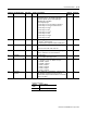
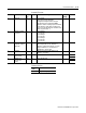
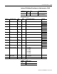
Instance 36 Attributes (Oscillography Configuration Read)
Assembly Structure
Common Services
Attribute ID Access
Rule
Nam
e
DeviceNet Data Type
3 Get Data Structure of
10 bytes (5 Words) (when Master Module firmware is
V2.10 or earlier)
14 bytes (7 Words) (when Master Module firmware is
V3.00 or later)
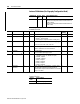
Param # Parameter name Data Type # bytes Description Default
Setting
Word No.
1 Password Int 2 Always returns –1 - 1
2 Buffer type Int 2 Indicates how captures are buffered.
0 = Hold (1
st
capture is held)
1 = Overwrite (new captures overwrite existing ones)
12
3 Channel A Int 2 Indicates signal for channel A when Oscillograph type =
0.
1=V1, 2=I1, 3=V2, 4=I2, 5=V3, 6=I3, 7=I4
13
4 Channel B Int 2 Indicates signal for channel B when Oscillograph type =
0.
Refer to ‘Channel A’ for a list of selections.
24
5 Pretrigger Int 2 -1 = No pretrig
0 to 8 = number of pre-trigger cycles
05
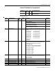
6
Oscillograph type
(1)
Int 2 0 = Master Module firmware V2.10 compatible mode
(7channel x 2 cycle + 2 channel x 12 cycle)
1 = 10.8kHz, 1 capture
2 = 10.8kHz, 2 captures
3 = 5.4kHz, 1 capture
4 = 5.4kHz, 2 captures
5 = 2.7kHz, 1 capture
6 = 2.7kHz, 2 captures
06
7 Overwrite
timeout
(1)
Int 2 When ‘Buffer Type’ is configured in ‘overwrite’ mode,
this parameter indicates the amount of time (in
minutes) that a capture will be held before it is cleared.
Range = 1 to 4320
17
(1) Available on master module firmware V3.00 or later (not implemented on previous versions)
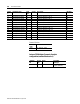
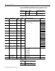
Service
Code
Service Name
0Ehex Get_Attributes_Single