
Installation Instructions Manual

Publication 1403-IN054A-EN-P - August 2001
1-6 Product Description
Wiring
For detailed DeviceNet system installations, including the placement
of termination resistors, refer to Publication DN-6.7.2.
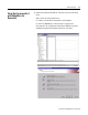
Configuration Items
Communication
The Powermonitor II communication parameters must be configured
before connecting the Powermonitor II to a DeviceNet network. Use
the Display Module under the Program > Communications menu.
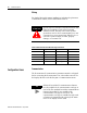
ATTENTION
Special high level isolation is required between units
when the possibility of high ground potential
differences exist. This may occur when separate
grounds are used or when communicating to a unit
connected to a power ground mat. Failure to do so
can lead to personal injury or death, property
damage, or economic loss.
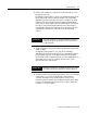
Table 1.3 DeviceNet Terminal Block Wiring Connections
Terminal Signal Function Color
1 COM Common Black
2 CAN_L Signal Low Blue
3 SHIELD Shield Uninsulated
4 CAN_H Signal High White
5 VDC+ Power Supply Red
TIP
Enhanced DeviceNet V2 communications features
are only available if the communication card type is
read as 88. The standard DeviceNet communications
features (DeviceNet V1) are available if the
communication card type is read as 81. The
communication card type is available through reads
of Instance 19 (parameter 14) or through the status
menu of the display module (DM).