Installation Instructions Bulletin 1403 DeviceNet™ Communications Card (Catalog Number 1403-NDNET) 1 Publication 1403-IN054B-EN-P
Bulletin 1403 DeviceNet™ Communications Card Important User Information Because of the variety of uses for the products described in this publication, those responsible for the application and use of this control equipment must satisfy themselves that all necessary steps have been taken to assure that each application and use meets all performance and safety requirements, including any applicable laws, regulations, codes and standards.
Table of Contents Product Description Chapter Objectives . . . . . . . . . . . . . . . . . . . . . . . . . . . . . . Terms and Conventions. . . . . . . . . . . . . . . . . . . . . . . . . . . Introduction . . . . . . . . . . . . . . . . . . . . . . . . . . . . . . . . . . . Features . . . . . . . . . . . . . . . . . . . . . . . . . . . . . . . . . . . . . . Installation . . . . . . . . . . . . . . . . . . . . . . . . . . . . . . . . . . . . Field Service Considerations . . . . . . . . . . . . . . . . . . .
Table of Contents ii Instance 8 Attributes (Advanced Configuration Data Read) . . . . . . . . . . . . . . . . . . . . . . B-11 Instance 9 Attributes (DeviceNet Communication Configuration Write) . . . . . . . . . . . . . B-13 Instance 10 Attributes (DeviceNet Communication Configuration Read) . . . . . . . . . . . . . . . . . . . . . . . . . . B-14 Instance 11 Attributes (Metering voltage, current, and frequency results) . . . . . . . . . . . . . . . . . . . . . . . . . . .
Table of Contents Instance 38 Attributes (harmonic Analysis configuration/readback data select) . . . . . . . . . . . . . . Instance 39 Attributes (Read of harmonic Analysis configuration) . . . . . . . . . . . . . . . . Instance 40 Attributes (THD, IEEE 519, Crest Factor, K-Factor) . . . . . . . . . . . . . . . . . . . . . . . . Instance 41 Attributes (Even harmonic data; harmonics 2-20). . . . . . . . . . . . . . . . . . . . . . . . . . . . . Instance 42 Attributes (Even harmonic data; harmonics 22-40) .
Table of Contents iv Class 2B - Acknowledge Handler Object . . . . . . . . . . . B-95 Appendix C DeviceNet Communication Card Sample Ladder Listing Ladder Program Description . . . . . . Explicit Message Transfer . . . . . . User Configurable Messages . . . . Multiple Powermonitor II Reads . . . . . . . . . . . . . . . . . . . . . . . . . . . . . . . . . . . . . . . . . . . . . . . . . . . . . . . . . . . . . . . . . . . . . C-1 C-1 C-5 C-8 Product Approvals . . . . . . . . . . . . .
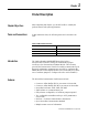
Chapter 1 Product Description Chapter Objectives After completing this chapter, you should be able to identify the product features and system applications. Terms and Conventions In this instruction sheet, the following terms and conventions are used: Table 1.
1-2 Product Description • Communications up to 500K baud; retrieve real-time power information in 33 ms • Supports a custom data table • Supports peer-to-peer communications using Explicit Server Messaging • Real-time diagnostic capabilities • C.O.S, Cyclic, and Polled I/O Messaging. • AutoBaud(1) • Remotely settable baud rate(1) • Remotely resettable through Identity Object(1) • Remotely settable Node Address(1) • Support for up to 4 concurrent clients(1) • Supports DeviceNet Heartbeat facility Figure 1.
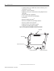
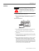
Product Description 1-3 Installation ATTENTION Please follow appropriate ESD procedures before removal and/or installation of the DeviceNet Communications Card. Failure to follow these procedures can result in physical damage to both the DeviceNet Communications Card and the Master Module. 1. Remove Master Module control power. 2. Remove the blank plate by unscrewing the two corner retaining screws as shown in Figure 1.2. Save these two screws for assembly. Figure 1.2 Blank Plate Removal 3.
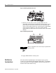
1-4 Product Description Figure 1.3 Installing Communication Card 7. Place the closure plate over the opening. Make sure the DeviceNet connector shows through the opening in the closure plate. Plug the DeviceNet connector into the DeviceNet port. Secure closure plate with the two screws from the original blank plate as shown in Figure 1.4. The closure plate extends approximately 20 mm (0.80 inches) from the back of the Master Module. Figure 1.
Product Description General Operation 1-5 Communications Card Set-Up All DeviceNet card configuration items such as node address, baud rate, and bus-off interrupt are set by configuring the Master Module. Indicators Two LED indicators provide information about the operating status of the card. Table 1.
1-6 Product Description Wiring For detailed DeviceNet system installations, including the placement of termination resistors, refer to Publication DN-6.7.2. ATTENTION Special high level isolation is required between units when the possibility of high ground potential differences exist. This may occur when separate grounds are used or when communicating to a unit connected to a power ground mat. Failure to do so can lead to personal injury or death, property damage, or economic loss. Table 1.
Product Description 1-7 1. Set the node address to a unique ID on the network (0 to 63). (Default is set to 63.) For Enhanced DeviceNet V2, there is an additional setting of 64. Node address 64 enables remotely settable node addressing. RSNetWorx for DeviceNet may be used to configure the node address of the Powermonitor II in this manner.
1-8 Product Description Table 1.4 Communication Configuration Items Publication 1403-IN054A-EN-P - August 2001 Communication Parameter Description New Node Address Enter the node address (0 to 64) (default is 63) of the Powermonitor II on the DeviceNet link. A node address change takes effect on reset. New Baud Rate The options are 125K, 250K, 500K, AUTO and PGM (default is 125K). The selected baud rate takes effect after a reset. The maximum cable length is restricted at higher baud rates.
Product Description Using the Powermonitor II with RSNetWorx for DeviceNet 1-9 1. Install Powermonitor II EDS file. This file can be downloaded from: http://www.ab.com/networks/eds or contact your Rockwell Automation representative. In order for RSNetWorx for DeviceNet to recognize the Powermontior II, an Electronic Data Sheet (EDS) file must be installed using the EDS Wizard under the Tools menu.
1-10 Product Description Publication 1403-IN054A-EN-P - August 2001
Product Description 1-11 Publication 1403-IN054A-EN-P - August 2001
1-12 Product Description 2. Scan the Powermonitor II. At this point, the DeviceNet scanner module does not know what device to scan. Click on the Online button to list the available devices on the network.
Product Description 1-13 3. Read the scanner’s configuration. Right click on the DeviceNet scanner icon and upload the scanner’s present configuration.
1-14 Product Description 4. Edit the Scanner List. The DeviceNet scanner needs to know how the information is coming from the Powermonitor II. Select the Scanlist tab and move the Powermonitor II into the Scanlist set.
Product Description 1-15 5. Edit the Data Table Map. The DeviceNet Scanner needs to know which bytes will be scanned from the Powermonitor II. Select the Input tab. This allows the user to determine where the informatin is stored inside the scanner module. When finished configuring, select the Apply button. 6. Download Configuration to the Scanner. All of the configuration data must be downloaded to the scanner module.
1-16 Product Description Publication 1403-IN054A-EN-P - August 2001
Product Description I/O Messaging 1-17 The Powermonitor II supports three types of I/O Messaging • Polled • Change of State (COS) • Cyclic The default setting is 8 Rx and 4 Tx bytes; however, the I/O Message is configurable up to 22 different parameters consisting of up to 64 words. These words can be retrieved from the DeviceNet scanner using block transfer reads for the PLC-5 or accessing the M1 file or input image table from the SLC-500.
1-18 Product Description Every Scan Polled I/O Messaging The optimal polling rate for the Every Scan message type is 28 ms. An Interscan Delay smaller than 28 ms causes the Powermonitor II to delay the update of its metering information. Background Polled I/O Messaging Background Polled I/O Messaging occurs after the specified number scans by setting the Foreground to Background Poll Ratio. As long as the total scan time is greater than 28 ms, the Powermonitor II communicates at its optimal speed.
Product Description 1-19 Change of State I/O Messaging The Powermonitor II supports Change of State (COS) I/O Messaging which reports data on a change-of-state basis as the events happen, rather than a master going through a polling list. Change of state messaging is typically more efficient for discrete applications; for network traffic is significantly reduced, and performance is greatly improved.
1-20 Product Description Cyclic I/O Messaging The Powermonitor II supports Cyclic I/O Messaging, which reports data on a user-configured time increment basis. Cyclic data messaging is more efficient for applications with slowly changing I/O (analog); network traffic is reduced and performance is repeatable.
Product Description 1-21 Powermonitor II without a Scanner The Powermonitor II can communicate directly to other DeviceNet devices, such as the PanelView family of products, without using a DeviceNet scanner module. The Powermonitor II accomplishes this by supporting Explicit Server Messaging, as shown below.
1-22 Product Description Publication 1403-IN054A-EN-P - August 2001
Appendix A Catalog Number Explanation Communications Cards 1403 - NDNET Bulletin Number 1403 = Powermonitor II Family of products. 1 Type of Device NDNET = Plug-in Communication Card for Bulletin 1403-MM and 1403-LM Devices (DeviceNet).
A-2 Catalog Number Explanation Publication 1403-IN054B-EN-P - August 2001
Appendix B DeviceNet Data Tables DeviceNet Information The 1403-NDNEToperates as a slave device on the DeviceNet network and supports I/O messaging (Polled, Change of State and Cyclic), Explicit Server Messaging and the xplicit Unconnected Message Manager (UCMM). This appendix defines the DeviceNet message types, class services, and objects supported by the 1403-NDNET. DeviceNet Message Types As a group 2 slave device, the 1403-NDNET supports the following message types.
B-2 DeviceNet Data Tables DeviceNet Object Classes The 1403-NDNET device supports the following DeviceNet object classes.
DeviceNet Data Tables Table Instance 28 Attributes (Power Factor Snapshot data) Instance 29 Attributes (Min/max configuration/readback parameter select) Available Min/Max Log Paramters Instance 30 Attributes (Read of Min/max configuration) Instance 31 Attributes (Min/Max log results) Instance 32 Attributes (Event log configuration/readback log select) Instance 33 Attributes (Read of Event log configuration) Instance 34 Attributes (Event log results) Instance 35 Attributes (Oscillography configuration/readb
B-4 DeviceNet Data Tables Class 4 - Assembly Objects Class Code: 04hex Number of Instances: 49 Instance 1 Attributes (Input Data Assembly) Attribute ID Access Rule 3 Get Name Data DeviceNet Data Type Structure of 8 bytes (64 Bits) Assembly Structure Param # 1 Parameter name Relay #1 status Data type Int #bytes 2 2 Relay #2 status Int 2 3 Alarm word Int 2 4 Status inputs Int 2 Comment 0 = De-energized 1 = Energized 2 = Forced De-energized 3 = Forced Energized 0 = De-energized 1 = Energ
DeviceNet Data Tables B-5 Instance 2 Attributes (Output Data Assembly) Attribute ID Access Rule 3 Set Name Data DeviceNet Data Type Structure of 4 bytes (32 Bits) Assembly Structure Param # Parameter name 1 2 Reserved Reserved Data type Int Int #bytes Word No.
B-6 DeviceNet Data Tables Param # Parameter name Data type #bytes Comment 13 14 15 16 17 18 19 20 21 22 23 24 25 26 Selection for parameter #9 Selection for parameter #10 Selection for parameter #11 Selection for parameter #12 Selection for parameter #13 Selection for parameter #14 Selection for parameter #15 Selection for parameter #16 Selection for parameter #17 Selection for parameter #18 Selection for parameter #19 Selection for parameter #20 Selection for parameter #21 Selection for parameter #
DeviceNet Data Tables Param # 8 9 10 11 12 13 14 15 16 17 18 19 20 21 22 23 24 25 26 Parameter name Selection for parameter #4 Selection for parameter #5 Selection for parameter #6 Selection for parameter #7 Selection for parameter #8 Selection for parameter #9 Selection for parameter #10 Selection for parameter #11 Selection for parameter #12 Selection for parameter #13 Selection for parameter #14 Selection for parameter #15 Selection for parameter #16 Selection for parameter #17 Selection for parameter
B-8 DeviceNet Data Tables Instance 5 Attributes (Basic Device Configuration Data Write) Attribute ID 3 Access Rule Set Name Data DeviceNet Data Type Structure of 40 bytes (20 Words) Assembly Structure Param # Parameter name Data type #bytes Master Module Range Default Setting 0 1 Present unit password Int 2 0 to 9999 required 2 New password Int 2 0 Word No.
DeviceNet Data Tables B-9 Instance 6 Attributes (Basic Device Configuration Data Read) Attribute ID 3 Access Rule Get Name Data DeviceNet Data Type Structure of 40 bytes (20 Words) Assembly Structure Param # Parameter name Data type #bytes Master Module Range Default Setting 0 0 4 1 2 3 Present unit password New password Voltage mode Int Int Int 2 2 2 4 Vaux voltage mode Int 2 5 L1/L1/L3 PT primary Float 4 PM-II will always return –1 PM-II will always return –1 0 = Demo 1 = Single 2
B-10 DeviceNet Data Tables Instance 7 Attributes (Advanced Configuration Data Write) Attribute ID 3 Access Rule Set Name Data DeviceNet Data Type Structure of 48 bytes (24 Words) Assembly Structure Param # Parameter name Data type #bytes Master Module Range 1 2 3 4 Password Demand period length Number of demand periods Output pulse relay # Int Int Int Int 2 2 2 2 5 Output pulse parameter Int 2 6 7 8 9 Output pulse increment Output pulse width Filter mode (1403-MM) Restore factory default
DeviceNet Data Tables Param # Parameter name Data type #bytes Master Module Range Default Setting 18 Set VAR hours Float 4 19 Set time/date 4 word 8 –9999x108 to +9999x10 8 Set to -1.0 for no effect on var-hour counter. Year Month, Day Hour, Minute Seconds, Hundredths B-11 Word No. 19 20 21 22 23 24 (1) On a read, returns the value of the status input counter.
B-12 DeviceNet Data Tables Param # Parameter name Data type #bytes 13 14 15 16 17 Unused Unused Unused Unused Unused Int Int Int Int Float 2 2 2 2 4 Master Module Range Returns 0 Returns 0 Returns 0 Returns 0 Returns 0 18 Unused Float 4 Returns 0 19 Time/date 4 word 8 Year Month, Day Hour, Minute Seconds, Hundredths Common Services Service Code 0Ehex Publication 1403-IN054B-EN-P - August 2001 Service Name Get_Attributes_Single Default Setting Word No.
DeviceNet Data Tables B-13 Instance 9 Attributes (DeviceNet Communication Configuration Write)(1) Attribute ID 3 Access Rule Set Name Data DeviceNet Data Type Structure of 10 bytes (5 Words) Assembly Structure Param # Parameter name Data type #bytes Master Module Range 1 2 Password Node address Int Int 2 2 3 Baud rate Int 2 4 Bus off interrupt Int 2 0 to 9999 required 0 to 63 (DeviceNet V1) 0 to 64 (DeviceNet V2)(1) 0 = 125k 1 = 250k 2 = 500k 3 = Auto (DeviceNet V2 only) 4 = Programma
B-14 DeviceNet Data Tables Instance 10 Attributes (DeviceNet Communication Configuration Read) Attribute ID Access Rule 3 Get Name DeviceNet Data Type Data Structure of 10 bytes (5 Words) Assembly Structure Param # Parameter name Data type #bytes Master Module Range Default Setting 1 2 Password Node address Int Int 2 2 3 Baud rate Int 2 4 Bus off interrupt Int 2 Always returns –1 0 to 63 (DeviceNet V1) 0 to 64 (DeviceNet V2)(1) 0 = 125k 1 = 250k 2 = 500k 3 = Auto (DeviceNet V2 only)
DeviceNet Data Tables Param # 3 Parameter name L3 current Data type Float #bytes 4 Master Module Range 0.0 to 4 Avg current Float 4 0.0 to 9999x1021 amps 6 L4 current Float 4 0.0 to 9999x1021 amps 7 L1-N voltage Float 4 0.0 to 9999x1021 volts 8 L2-N voltage Float 4 0.0 to 9999x1021 volts 9 L3-N voltage Float 4 0.0 to 9999x1021 volts 10 Ave L-N voltage Float 4 0.0 to 9999x1021 volts 11 L1-L2 voltage Float 4 0.0 to 9999x1021 volts 12 L2-L3 voltage Float 4 0.
B-16 DeviceNet Data Tables Instance 12 Attributes (Sequence voltages and currents) Attribute ID Access Rule 3 Get Name DeviceNet Data Type Data Structure of 36 bytes (18 Words) Assembly Structure Param # 1 Parameter name Positive sequence voltage 2 Data type Float #bytes 4 Master Module Range 0.0 to 9999x10 volts Negative sequence voltage Float 4 0.0 to 9999x1021 volts 3 AUX voltage Float 4 0.0 to 9999x1021 volts 4 % voltage unbalance Float 4 0.0 to 100.
DeviceNet Data Tables B-17 Instance 13 Attributes (Metering power results) Attribute ID Access Rule 3 Get Name DeviceNet Data Type Data Structure of 50 bytes (25 Words) Assembly Structure Param # 1 Parameter name L1 real power Data type Float #bytes 4 0.0 to 9999x10 W 2 L2 real power Float 4 0.0 to 9999x1021 W 3 L3 real power Float 4 0.0 to 9999x1021 W 4 Total real power Float 4 0.0 to 9999x1021 W 5 L1 reactive power Float 4 0.
B-18 DeviceNet Data Tables Instance 14 Attributes (Metering power factor results) Attribute ID Access Rule 3 Get Name DeviceNet Data Type Data Structure of 50 bytes (25 Words) Assembly Structure Param # Parameter name Data type #bytes Master Module Range 1 L1 true power factor Float 4 –100.0 to +100.0 2 L2 true power factor Float 4 –100.0 to +100.0 3 L3 true power factor Float 4 –100.0 to +100.0 4 3-phase true power factor Float 4 –100.0 to +100.
DeviceNet Data Tables B-19 Instance 15 Attributes (Metering real energy results) Attribute ID Access Rule 3 Get Name DeviceNet Data Type Data Structure of 32 bytes (16 Words) Assembly Structure Param # Parameter name Data type #bytes Master Module Range Word No. Range Modulu s 1 KWh forward Modulus 10 0 to 1.
B-20 DeviceNet Data Tables Instance 16 Attributes (Metering reactive energy results) Attribute ID Access Rule 3 Get Name DeviceNet Data Type Data Structure of 32 bytes (16 Words) Assembly Structure Param # Parameter name Data type #bytes Master Module Range Word No. Range Modulu s 1 KVARh forward Modulus 10 0 to 1.
DeviceNet Data Tables B-21 Instance 17 Attributes (Metering demand results) Attribute ID Access Rule 3 Get Name DeviceNet Data Type Data Structure of 18 bytes (9 Words) Assembly Structure Param # 1 Parameter name Demand current Data type Float #bytes 4 2 Demand power Float 4 3 Demand reactive power Float 4 4 Demand apparent power Float 4 5 Metering iteration 2 Int Master Module Range Word No. 1 0.0 to 9999x10 amps 2 21 3 0.0 to 9999x10 W 4 21 5 0.0 to 9999x10 VAR 6 21 7 0.
B-22 DeviceNet Data Tables Param # 5 Parameter name Projected #2 demand I Data type Float #bytes 4 6 Projected #2 demand W Float 4 7 Projected #2 demand VAR Float 4 8 Projected #2 demand VA Float 4 9 Projected #3 demand I Float 4 10 Projected #3 demand W Float 4 11 Projected #3 demand VAR Float 4 12 Projected #3 demand VA Float 4 13 Elapsed time Float 4 14 Metering iteration Int 2 Master Module Range Word No. 9 0.0 to 10 21 11 0.0 to 9999x10 W 12 21 13 0.
DeviceNet Data Tables Param # 9 10 11 12 13 14 Parameter name Data acquisition Master module watchdog Real-time clock status Battery usage Comm card status Comm card type Data type Int Int Int Int Int Int #bytes 2 2 2 2 2 2 15 16 17 18 19 20 21 22 23 24 Comm card FRN Number of display modules Display module status DM selftest results; word 1 DM selftest results; word 2 DM selftest results; word 3 DM #1 firmware revision DM #2 firmware revision DM #3 firmware revision Fiber loopback test result Int In
B-24 DeviceNet Data Tables Instance 20 Attributes (Setpoint setup/readback select) Attribute ID 3 Access Rule Set Name Data DeviceNet Data Type Structure of 24 bytes (14 Words) Assembly Structure Param # Parameter name Data type #bytes Master Module Range 1 Password Int 2 2 Setpoint number to readback Setpoint number to config Setpoint type Setpoint evaluation condition Int 2 -1, 0 to 9999 Correct password is required to configure/reconfigure a setpoint, but not required to select a setpo
DeviceNet Data Tables B-25 Instance 21 Attributes (Setpoint configuration read) Attribute ID Access Rule 3 Get Name DeviceNet Data Type Data Structure of 24 bytes (12 Words) Assembly Structure Param # 1 2 3 4 5 Parameter name Setpoint number being read Setpoint type Data type Int #bytes 2 Int 2 Setpoint evaluation condition Int 2 Master Module Range From parameter 2 of the most recent valid write of Table 20 above. 0 to 54 (see Table B.26 in Publication 1403-5.
B-26 DeviceNet Data Tables Instance 22 Attributes (Setpoint status information) Attribute ID Access Rule 3 Get Name DeviceNet Data Type Data Structure of 40 bytes (20 Words) Assembly Structure Param # 1 2 3 4 5 6 7 8 9 10 11 12 13 14 15 16 17 18 19 20 Parameter name Setpoint #1 status Setpoint #2 status Setpoint #3 status Setpoint #4 status Setpoint #5 status Setpoint #6 status Setpoint #7 status Setpoint #8 status Setpoint #9 status Setpoint #10 status Setpoint #11 status Setpoint #12 status Setpoi
DeviceNet Data Tables B-27 Instance 23 Attributes (Snapshot configuration/readback record select) Attribute ID 3 Access Rule Set Name Data DeviceNet Data Type Structure of 14 bytes (7 Words) (when Master Module firmware is V2.10 or earlier) 22 bytes (11 Words) (when Master Module firmware is V3.
B-28 DeviceNet Data Tables Param # Parameter name Data Type # bytes Description 8 Snapshot log type(1) Int 2 9 Snapshot param #1(1) Int 2 10 Snapshot param #2(1) Int 2 11 Snapshot param #3(1) Int 2 Determines how many parameters are stored in each snapshot record.
DeviceNet Data Tables B-29 Assembly Structure Param # Parameter name Data Type # bytes Description 1 Snapshot interval; hours Snapshot interval; minutes Snapshot interval; seconds Snapshot buffer type Int 2 Int 2 Int 2 Int 2 #Records in Snapshot Log Snapshot log type(1) Int 2 Int 2 7 Snapshot param #1(1) Int 2 8 Snapshot param #2(1) Int 2 9 Snapshot param #3(1) Int 2 2 3 4 5 6 Default Setting Word No.
B-30 DeviceNet Data Tables Snapshot log record parameter list Param # 0 1 2 3 4 5 6 7 8 9 10 11 12 13 14 15 16 17 18 19 20 21 22 23 24 25 Parameter name L1 Current L2 Current L3 Current Avg Current L4 Current L1-N Voltage L2-N Voltage L3-N Voltage Avg L-N Voltage L1-L2 Voltage L2-L3 Voltage L3-L1 Voltage Avg L-L Voltage Frequency Pos Seq Current Neg Seq Current Current Unbalance Pos Seq Voltage Neg Seq Voltage Voltage Unbalance Aux Voltage Aux Frequency L1 Real Power L2 Real Power L3 Real Power Total Rea
DeviceNet Data Tables B-31 Instance 25 Attributes (Voltage & Current Snapshot data) Attribute ID 3 Access Rule Get Name DeviceNet Data Type Data Structure of 58 bytes (29 Words) Assembly Structure Param # 1 Parameter name L1 current Data type Float #bytes 4 Master Module Range 0.0 to 9999x10 amps 2 L2 current Float 4 0.0 to 9999x1021 amps 3 L3 current Float 4 0.0 to 9999x1021 amps 4 Avg current Float 4 0.0 to 9999x1021 amps 5 L1-L2 voltage Float 4 0.
B-32 DeviceNet Data Tables Instance 26 Attributes (L4, Unbalance & Frequency Snapshot data) Attribute ID Access Rule 3 Get Name DeviceNet Data Type Data Structure of 52 bytes (26 Words) Assembly Structure Param # 1 Parameter name L4 current Data type Float #bytes 4 Master Module Range 0.0 to 2 Positive sequence current Float 4 0.0 to 9999x1021 amps 3 Negative sequence current Float 4 0.0 to 9999x1021 amps 4 % current unbalance Float 4 0.0 to 100.0 5 AUX voltage Float 4 0.
DeviceNet Data Tables B-33 Instance 27 Attributes (Power Snapshot data) Attribute ID Access Rule 3 Get Name DeviceNet Data Type Data Structure of 58 bytes (29 Words) Assembly Structure Param # 1 Parameter name L1 real power Data type Float #bytes 4 Master Module Range 0.0 to 9999x10 W 2 L2 real power Float 4 0.0 to 9999x1021 W 3 L3 real power Float 4 0.0 to 9999x1021 W 4 Total real power Float 4 0.0 to 9999x1021 W 5 L1 reactive power Float 4 0.
B-34 DeviceNet Data Tables Instance 28 Attributes (Power Factor Snapshot data) Attribute ID Access Rule 3 Get Name DeviceNet Data Type Data Structure of 58 bytes (29 Words) Assembly Structure Param # Parameter name Data type #bytes Master Module Range 1 L1 true power factor Float 4 –100.0 to +100.0 2 L2 true power factor Float 4 –100.0 to +100.0 3 L3 true power factor Float 4 –100.0 to +100.0 4 Total true power factor Float 4 –100.0 to +100.
DeviceNet Data Tables B-35 Instance 29 Attributes (Min/max configuration/readback parameter select) Attribute ID 3 Access Rule Set Name Data DeviceNet Data Type Structure of 8 bytes (4 Words) Assembly Structure Param # Parameter name Data type #bytes Master Module Range 1 Password Int 2 2 Min/max parameter Int record to be read 2 3 Enable/disable min/max log Clear min/max log Int 2 Int 2 -1, 0-9999 Correct password is required to configure/reconfigure min/max functionality, but not r
B-36 DeviceNet Data Tables Available Min/Max Log Paramters Parameter Number 1 2 3 4 5 6 7 8 9 10 11 12 13 14 15 16 17 18 19 20 21 22 23 24 25 26 27 28 29 30 31 32 33 34 35 36 37 38 39 40 41 42 Parameter Description Phase 1 current Phase 2 current Phase 3 current Phase 4 current Average current Positive sequence current Negative sequence current Current unbalance Phase 1 L-L voltage Phase 2 L-L voltage Phase 3 L-L voltage Auxiliary voltage Average L-L voltage Positive sequence voltage Negative sequence vo
DeviceNet Data Tables B-37 Instance 30 Attributes (Read of Min/max configuration) Attribute ID Access Rule 3 Get Name DeviceNet Data Type Data Structure of 10 bytes (2 Words) Assembly Structure Param # Parameter name Data type #bytes Master Module Range 1 Enable/disable min/max log Int 2 2 Timestamp of last min/max clear Int x 4 8 0 = Disable 1 = Enable Year Month, Day Hour, Minute Seconds, Hundredths Default Setting 1 Word No.
B-38 DeviceNet Data Tables Param # 5 Parameter name Timestamp of last Min/Max reset Data type Int x 4 #bytes 8 6 Parameter # being returned Int x 4 8 Master Module Range Year Month, Day Hour, Minutes Seconds, Hundredths 1 to 84 Word No.
DeviceNet Data Tables B-39 Instance 33 Attributes (Read of Event log configuration) Attribute ID Access Rule 3 Get Name DeviceNet Data Type Data Structure of 4 bytes (2 Words) Assembly Structure Param # Parameter name Data type #bytes Master Module Range 1 Enable/disable save of status input changes to event log Number of events in the event log Int 2 0 = disable 1 = enable Int 2 0 - 100 2 Default Setting 0 Word No.
B-40 DeviceNet Data Tables Param # 10 11 Parameter name Setpoint action Setpoint level (float value) Data type Int Float #bytes 2 4 Master Module Range 0 to 20 ±9999.0x1021 If limit stored in event log is an integer, this returns to 0. Word No.
DeviceNet Data Tables Param # Parameter name Data Type # bytes Description 5 Data block to get Int 2 6 Buffer type Int 2 7 Channel A Int 2 8 Channel B Int 2 9 Pretrigger Int 2 10 Oscillograph type(1) Int 2 11 Overwrite timeout(1) 2 Int Specifies which portion of the capture to get during a subsequent read of .
B-42 DeviceNet Data Tables Instance 36 Attributes (Oscillography Configuration Read) Attribute ID Access Rule 3 Get Nam e Data DeviceNet Data Type Structure of 10 bytes (5 Words) (when Master Module firmware is V2.10 or earlier) 14 bytes (7 Words) (when Master Module firmware is V3.
DeviceNet Data Tables B-43 Instance 37 Attributes (Oscillography data) Attribute ID Access Rule 3 Get Name DeviceNet Data Type Data Structure of 50 bytes (25 Words) Assembly Structure Param # 1 Parameter name Timestamp of Oscillogram Data Type Int x 4 # bytes Description Word No.
B-44 Param # 10 11 12 13 14 15 16 17 18 19 20 21 22 DeviceNet Data Tables Parameter name Oscillogram data point 6 Oscillogram data point 7 Oscillogram data point 8 Oscillogram data point 9 Oscillogram data point 10 Oscillogram data point 11 Oscillogram data point 12 Oscillogram data point 13 Oscillogram data point 14 Oscillogram data point 15 Oscillogram data point 16 Oscillogram data point 17 Oscillogram data point 18 Data Type Int Int Int Int Int Int Int Int Int Int Int Int Int # bytes Description
DeviceNet Data Tables B-45 Assembly Structure Param # Parameter name Data type Int #bytes Master Module Range 1 Password 2 Harmonic channel to be read Default Setting 0 2 Int 2 3 Read % distortion, Int magnitude, or phase angle data 2 4 Reserved Int 2 5 IEEE 519 max short circuit current Float 4 -1, 0 to 9999 Correct password is required to configure/reconfigure harmonic Analysis functionality, but not required to select harmonic channel or data group to be read back in the harmoni
B-46 DeviceNet Data Tables Instance 39 Attributes (Read of harmonic Analysis configuration) Attribute ID Access Rule 3 Get Name DeviceNet Data Type Data Structure of 12 bytes (6 Words) Assembly Structure Param # Parameter name Data type #bytes Master Module Range Default Setting 1 Reserved Int 2 2 3 Reserved IEEE 519 max short circuit current Int Float 2 4 Reserved for future enable/disable of all harmonic calculations. Reserved 0.0 to 10,000,000.
DeviceNet Data Tables Param # 6 Parameter name IEEE 519 pass/fail Data type Int #bytes 2 7 Channel # returned Int 2 8 FFT iteration Int 2 Master Module Range –1 = Unknown 0 = Fail 1 = Pass 1 = L1 Voltage 2 = L1 Current 3 = L2 Voltage 4 = L2 Current 5 = L3 Voltage 6 = L3 Current 7 = L4 Current 0 to 32767 B-47 Word No.
B-48 DeviceNet Data Tables Assembly Structure Param # Parameter name #bytes Master Module Range Fundamental Data type Float 1 4 2 2nd harmonic Float 4 3 4th harmonic Float 4 4 6th harmonic Float 4 5 8th harmonic Float 4 6 10th harmonic Float 4 7 12th harmonic Float 4 8 14th harmonic Float 4 9 16th harmonic Float 4 10 18th harmonic Float 4 11 20th harmonic Float 4 12 Channel # returned Int 2 13 Type of harmonic data returned FFT iteration Int 2 Int 2
DeviceNet Data Tables B-49 Instance 42 Attributes (Even harmonic data; harmonics 22-40) Attribute ID Access Rule 3 Get Name DeviceNet Data Type Data Structure of 46 bytes (23 Wordss) Assembly Structure Param # Parameter name #bytes 22nd harmonic Data type Float 1 2 24th harmonic Float 4 3 26th harmonic Float 4 4 28th harmonic Float 4 5 30th harmonic Float 4 6 32nd harmonic Float 4 7 34th harmonic Float 4 8 36th harmonic Float 4 9 38th harmonic Float 4 10 40th har
B-50 DeviceNet Data Tables Instance 43 Attributes (Odd harmonic data; harmonics 1-21) Attribute ID Access Rule 3 Get Name DeviceNet Data Type Data Structure of 50 bytes (25 Words) Assembly Structure Param # Parameter name #bytes Master Module Range Fundamental Data type Float 1 4 2 3rd harmonic Float 4 3 5th harmonic Float 4 4 7th harmonic Float 4 5 9th harmonic Float 4 6 11th harmonic Float 4 7 13th harmonic Float 4 8 15th harmonic Float 4 9 17th harmonic Float
DeviceNet Data Tables B-51 Instance 44 Attributes (Odd harmonic data; harmonics 23-41) Attribute ID Access Rule 3 Get Name DeviceNet Data Type Data Structure of 46 bytes (23 Words) Assembly Structure Param # Parameter name #bytes 23rd harmonic Data type Float 1 2 25th harmonic Float 4 3 27th harmonic Float 4 4 29th harmonic Float 4 5 31st harmonic Float 4 6 33rd harmonic Float 4 7 35th harmonic Float 4 8 37th harmonic Float 4 9 39th harmonic Float 4 10 41st harmo
B-52 DeviceNet Data Tables Instance 45 Attributes (Write error status) Attribute ID Access Rule 3 Get Name DeviceNet Data Type Data Structure of 4 bytes (2 Words) Assembly Structure Param # Parameter name #bytes Master Module Range Word No. Channel number Data type Int 1 2 1 Parameter number Int 2 Indicates the channel number which was written to last. If most recent write contains an error, this indicates the first parameter which was not acceptable.
DeviceNet Data Tables Param # Parameter name Data type Float #bytes Master Module Range 5 L1 L2 L3 frequency (10-cycle average) 4 20.0 to 132.0 6 Phase rotation Int 2 Metering iteration Int 2 0 = No Rotation 1 = ABC 2 = ACB Used by external device to determine if it has new metering data. Counts from 0 to 32767, then rolls over to 0. 7 B-53 Word No.
B-54 DeviceNet Data Tables Common Services Service Code 0Ehex Service Name Get_Attributes_Single Instance 48 Attributes (Metering assembly maximized for quantity of parameters) Attribute ID Access Rule 3 Get Name DeviceNet Data Type Data Structure of 128 bytes (64 Words) Assembly Structure Param # Parameter name #bytes Master Module Range Word No. L1 current Data type Float 1 4 0.0 to 9999x1021 amps 2 L2 current Float 4 0.0 to 9999x1021 amps 3 L3 current Float 4 0.
DeviceNet Data Tables Param # Parameter name #bytes Master Module Range Word No. AUX voltage Data type Float 15 4 0.0 to 9999x1021 volts 16 L1 real power Float 4 0.0 to 9999x1021 W 17 l2 real power Float 4 0.0 to 9999x1021 W 18 L3 real power Float 4 0.0 to 9999x1021 W 19 Total real power Float 4 0.0 to 9999x1021 W 20 L1 reactive power Float 4 0.0 to 9999x1021 VAR 21 L2 reactive power Float 4 0.0 to 9999x1021 VAR 22 L3 reactive power Float 4 0.
B-56 DeviceNet Data Tables Instance 49 Attributes (User-configured message) Param # 1 2 3 4 5 6 7 8 9 10 N Parameter name User Defined User Defined User Defined User Defined User Defined User Defined User Defined User Defined User Defined User Defined User Defined Data type User Defined User Defined User Defined User Defined User Defined User Defined User Defined User Defined User Defined User Defined User Defined #bytes Master Module Range Word No.
DeviceNet Data Tables Param # 7 Parameter name Data Type Float L4 Current # bytes Description 4 RMS current measured via the I4+/I4- terminals 8 Voltage Unbalance Float 4 Range = 0 to 9999x1021 Amps Range = 0.0 to 100% 9 Current Unbalance Float 4 Range = 0.
B-58 Param # 7 8 9 10 DeviceNet Data Tables Parameter name # bytes Description VARh net Data Type Float 4 Range = -9999 x1021 to 9999x1021 VARh Record Timestamp; Year Record Timestamp; Month, Day Int Int 8 Record Timestamp; Hour, Minute Int Record Timestamp; Seconds, hSeconds Int Snashot record # being returned Unused Int Int Year Month = Value/256 Day = Remainder of Value/256 Hour = Value/256 Minute = Remainder of Value/256 Seconds = Value/256 HSeconds = Remainder of Value/256 Range 1 t
DeviceNet Data Tables Param # 9 10 11 Parameter name Record Timestamp; Year Record Timestamp; Month, Day Data Type Int Int Record Timestamp; Hour, Minute Int Record Timestamp; Seconds, hSeconds Int Snashot record # being returned Unused Int Int # bytes Description 8 Year Month = Value/256 Day = Remainder of Value/256 Hour = Value/256 Minute = Remainder of Value/256 Seconds = Value/256 HSeconds = Remainder of Value/256 Range 1 to 489 0 2 2 B-59 Word No.
B-60 DeviceNet Data Tables Instance 54 Attribute (Snapshot 3&7 parameter record) Attribute Access Name ID Rule 3 Get Data DeviceNet Data Type Structure of 52 bytes; 26 words Note: this table is only supported when master module firmware is V3.
DeviceNet Data Tables B-61 Instance 55 Attribute (Snapshot 1 parameter record) Attribute ID 3 Access Name Rule Get Data DeviceNet Data Type Structure of 28 bytes; 14 words Note: this table is only supported when master module firmware is V3.
B-62 DeviceNet Data Tables Param # 15 16 17 18 19 20 21 22 23 24 25 26 27 28 29 30 31 32 33 34 35 36 37 38 39 40 41 42 43 44 45 46 47 48 49 50 51 52 53 54 55 56 57 58 Parameter name Demand period length Number of demand periods Output pulse relay # Output pulse parameter Output pulse increment Output pulse width Filter mode (1403-MM) or enable THD (1403-LM) Counter for status input #1 Counter for status input #2 Counter for status input #3 Counter for status input #4 Battery usage timer Time/date Node ad
DeviceNet Data Tables Param # 59 60 61 62 63 64 65 66 67 68 69 70 71 72 73 74 75 76 77 78 79 80 81 82 83 84 85 86 87 88 89 90 91 92 93 94 95 96 97 98 99 100 101 102 103 Parameter name L1 reactive power L2 reactive power L3 reactive power Total reactive power L1 apparent power L2 apparent power L3 apparent power Total apparent power L1 true power factor L2 true power factor L3 true power factor 3-phase true power factor L1 displacement power factor L2 displacement power factor L3 displacement power factor
B-64 DeviceNet Data Tables Param # 104 105 106 107 108 109 110 111 112 113 114 115 116 117 118 119 120 121 122 123 124 125 126 127 128 129 130 131 132 133 134 135 136 137 138 139 140 141 142 143 144 145 146 147 148 Parameter name Options bit field Summary status Master module ROM status Master module RAM status NV RAM status Power supply check Data acquisition Master module watchdog Real-time clock status Battery usage Comm card status Comm card type Comm card FRN Number of display modules Display module
DeviceNet Data Tables Param # 149 150 151 152 153 154 155 156 Data type Int Int Int Int Int Int Int x 4 Int #bytes 2 2 2 2 2 2 8 2 Comment See Instance 25, parameter 1 See Instance 25, parameter 2 See Instance 25, parameter 3 See Instance 25, parameter 4 See Instance 25, parameter 5 See Instance 31, parameter 1 See Instance 31, parameter 2 See Instance 34, parameter 1 2nd harmonic Int Int Int Int Int Float Float Float Float Float Float Float Int Float Float 2 2 2 2 2 4 4 4 4 4 4 4 4 4 4 See Instance
B-66 DeviceNet Data Tables Param # Parameter name 189 20th harmonic 190 21st harmonic Data type #bytes Comment Float 4 See Instance 41, parameter 11 (% harmonic distortion for V1) Float 4 See Instance 43, parameter 11 (% harmonic distortion for V1) 191 22nd harmonic Float 4 See Instance 42, parameter 1 (% harmonic distortion for V1) 192 23rd harmonic Float 4 See Instance 44, parameter 1 (% harmonic distortion for V1) 193 24th harmonic Float 4 See Instance 42, parameter 2 (% harmonic dist
DeviceNet Data Tables Param # Parameter name 227 16th harmonic 228 17th harmonic Data type #bytes Comment Float 4 See Instance 41, parameter 9 (harmonic magnitude for V1) Float 4 See Instance 43, parameter 9 (harmonic magnitude for V1) 229 18th harmonic Float 4 See Instance 41, parameter 10 (harmonic magnitude for V1) 230 19th harmonic Float 4 See Instance 43, parameter 10 (harmonic magnitude for V1) 231 20th harmonic Float 4 See Instance 41, parameter 11 (harmonic magnitude for V1) 232
B-68 DeviceNet Data Tables Param # Parameter name 265 13th harmonic 266 14th harmonic Data type #bytes Comment Float 4 See Instance 43, parameter 7 (phase angle for V1) Float 4 See Instance 41, parameter 8 (phase angle for V1) 267 15th harmonic Float 4 See Instance 43, parameter 8 (phase angle for V1) 268 16th harmonic Float 4 See Instance 41, parameter 9 (phase angle for V1) 269 17th harmonic Float 4 See Instance 43, parameter 9 (phase angle for V1) 270 18th harmonic Float 4 See In
DeviceNet Data Tables Param # Parameter name 304 5th harmonic 305 6th harmonic B-69 Data type #bytes Comment Float 4 See Instance 43, parameter 3 (% harmonic distortion for I1) Float 4 See Instance 41, parameter 4 (% harmonic distortion for I1) 306 7th harmonic Float 4 See Instance 43, parameter 4 (% harmonic distortion for I1) 307 8th harmonic Float 4 See Instance 41, parameter 5 (% harmonic distortion for I1) 308 9th harmonic Float 4 See Instance 43, parameter 5 (% harmonic distortion
B-70 DeviceNet Data Tables Param # Parameter name 342 Fundamental 343 2nd harmonic 344 3rd harmonic Data type #bytes Comment Float 4 See Instance 43, parameter 1 (harmonic magnitude for I1) Float 4 See Instance 41, parameter 2 (harmonic magnitude for I1) Float 4 See Instance 43, parameter 2 (harmonic magnitude for I1) 345 4th harmonic Float 4 See Instance 41, parameter 3 (harmonic magnitude for I1) 346 5th harmonic Float 4 See Instance 43, parameter 3 (harmonic magnitude for I1) 347 6 harmo
DeviceNet Data Tables Param # Parameter name 380 39th harmonic 381 40th harmonic Data type #bytes Comment Float 4 See Instance 44, parameter 9 (harmonic magnitude for I1) Float 4 See Instance 42, parameter 10 (harmonic magnitude for I1) Float 4 See Instance 44, parameter 10 (harmonic magnitude for I1) 2 harmonic Float Float 4 4 See Instance 43, parameter 1 (phase angle for I1) See Instance 41, parameter 2 (phase angle for I1) 385 3rd harmonic Float 4 See Instance 43, parameter 2 (phase angle
B-72 DeviceNet Data Tables Param # Parameter name 418 36th harmonic 419 37th harmonic Data type #bytes Comment Float 4 See Instance 42, parameter 8 (phase angle for I1) Float 4 See Instance 44, parameter 8 (phase angle for I1) 420 38th harmonic Float 4 See Instance 42, parameter 9 (phase angle for I1) 421 39th harmonic Float 4 See Instance 44, parameter 9 (phase angle for I1) 422 40th harmonic Float 4 See Instance 42, parameter 10 (phase angle for I1) 423 41st harmonic IEEE THD IEC thd
DeviceNet Data Tables Param # Parameter name 457 28th harmonic 458 29th harmonic B-73 Data type #bytes Comment Float 4 See Instance 42, parameter 4 (% harmonic distortion for V2) Float 4 See Instance 44, parameter 4 (% harmonic distortion for V2) 459 30th harmonic Float 4 See Instance 42, parameter 5 (% harmonic distortion for V2) 460 31st harmonic Float 4 See Instance 44, parameter 5 (% harmonic distortion for V2) 461 32nd harmonic Float 4 See Instance 42, parameter 6 (% harmonic distor
B-74 DeviceNet Data Tables Param # Parameter name 495 24th harmonic 496 25th harmonic Data type #bytes Comment Float 4 See Instance 42, parameter 2 (harmonic magnitude for V2) Float 4 See Instance 44, parameter 2 (harmonic magnitude for V2) 497 26th harmonic Float 4 See Instance 42, parameter 3 (harmonic magnitude for V2) 498 27th harmonic Float 4 See Instance 44, parameter 3 (harmonic magnitude for V2) 499 28th harmonic Float 4 See Instance 42, parameter 4 (harmonic magnitude for V2) 5
DeviceNet Data Tables Param # Parameter name 533 21st harmonic 534 22nd harmonic Data type #bytes Comment Float 4 See Instance 43, parameter 11 (phase angle for V2) Float 4 See Instance 42, parameter 1 (phase angle for V2) 535 23rd harmonic Float 4 See Instance 44, parameter 1 (phase angle for V2) 536 24th harmonic Float 4 See Instance 42, parameter 2 (phase angle for V2) 537 25th harmonic Float 4 See Instance 44, parameter 2 (phase angle for V2) 538 26th harmonic Float 4 See Instanc
B-76 DeviceNet Data Tables Param # Parameter name 572 13th harmonic 573 14th harmonic Data type #bytes Comment Float 4 See Instance 43, parameter 7 (% harmonic distortion for I2) Float 4 See Instance 41, parameter 8 (% harmonic distortion for I2) 574 15th harmonic Float 4 See Instance 43, parameter 8 (% harmonic distortion for I2) 575 16th harmonic Float 4 See Instance 41, parameter 9 (% harmonic distortion for I2) 576 17th harmonic Float 4 See Instance 43, parameter 9 (% harmonic distor
DeviceNet Data Tables Param # Parameter name 610 9th harmonic 611 10th harmonic Data type #bytes Comment Float 4 See Instance 43, parameter 5 (harmonic magnitude for I2) Float 4 See Instance 41, parameter 6 (harmonic magnitude for I2) 612 11th harmonic Float 4 See Instance 43, parameter 6 (harmonic magnitude for I2) 613 12th harmonic Float 4 See Instance 41, parameter 7 (harmonic magnitude for I2) 614 13th harmonic Float 4 See Instance 43, parameter 7 (harmonic magnitude for I2) 615 14t
B-78 DeviceNet Data Tables Param # Parameter name 648 6th harmonic 649 7th harmonic Data type #bytes Comment Float 4 See Instance 41, parameter 4 (phase angle for I2) Float 4 See Instance 43, parameter 4 (phase angle for I2) 650 8th harmonic Float 4 See Instance 41, parameter 5 (phase angle for I2) 651 9th harmonic Float 4 See Instance 43, parameter 5 (phase angle for I2) 652 10th harmonic Float 4 See Instance 41, parameter 6 (phase angle for I2) 653 11th harmonic Float 4 See Instan
DeviceNet Data Tables Param # 686 687 688 689 690 691 Parameter name TIF Crest factor K-factor IEEE 519 pass/fail Fundamental B-79 2nd harmonic Data type Float Float Float Int Float Float #bytes 4 4 4 4 4 4 Comment See Instance 40, parameter 3 (for V3) See Instance 40, parameter 4 (for V3) See Instance 40, parameter 5 (for V3) See Instance 40, parameter 6 (for V3) See Instance 43, parameter 1 (% harmonic distortion for V3) See Instance 41, parameter 2 (% harmonic distortion for V3) 692 3rd harmonic
B-80 DeviceNet Data Tables Param # Parameter name 724 35th harmonic 725 36th harmonic Data type #bytes Comment Float 4 See Instance 44, parameter 7 (% harmonic distortion for V3) Float 4 See Instance 42, parameter 8 (% harmonic distortion for V3) 726 37th harmonic Float 4 See Instance 44, parameter 8 (% harmonic distortion for V3) 727 38th harmonic Float 4 See Instance 42, parameter 9 (% harmonic distortion for V3) 728 39th harmonic Float 4 See Instance 44, parameter 9 (% harmonic distor
DeviceNet Data Tables Param # Parameter name 762 31st harmonic 763 32nd harmonic Data type #bytes Comment Float 4 See Instance 44, parameter 5 (harmonic magnitude for V3) Float 4 See Instance 42, parameter 6 (harmonic magnitude for V3) 764 33rd harmonic Float 4 See Instance 44, parameter 6 (harmonic magnitude for V3) 765 34th harmonic Float 4 See Instance 42, parameter 7 (harmonic magnitude for V3) 766 35th harmonic Float 4 See Instance 44, parameter 7 (harmonic magnitude for V3) 767 36
B-82 DeviceNet Data Tables Param # Parameter name 800 28th harmonic 801 29th harmonic Data type #bytes Comment Float 4 See Instance 42, parameter 4 (phase angle for V3) Float 4 See Instance 44, parameter 4 (phase angle for V3) 802 30th harmonic Float 4 See Instance 42, parameter 5 (phase angle for V3) 803 31st harmonic Float 4 See Instance 44, parameter 5 (phase angle for V3) 804 32nd harmonic Float 4 See Instance 42, parameter 6 (phase angle for V3) 805 33rd harmonic Float 4 See In
DeviceNet Data Tables Param # Parameter name 839 20th harmonic 840 21st harmonic Data type #bytes Comment Float 4 See Instance 41, parameter 11 (% harmonic distortion for I3) Float 4 See Instance 43, parameter 11 (% harmonic distortion for I3) 841 22nd harmonic Float 4 See Instance 42, parameter 1 (% harmonic distortion for I3) 842 23rd harmonic Float 4 See Instance 44, parameter 1 (% harmonic distortion for I3) 843 24th harmonic Float 4 See Instance 42, parameter 2 (% harmonic distortion
B-84 DeviceNet Data Tables Param # Parameter name 877 16th harmonic 878 17th harmonic Data type #bytes Comment Float 4 See Instance 41, parameter 9 (harmonic magnitude for I3) Float 4 See Instance 43, parameter 9 (harmonic magnitude for I3) 879 18th harmonic Float 4 See Instance 41, parameter 10 (harmonic magnitude for I3) 880 19th harmonic Float 4 See Instance 43, parameter 10 (harmonic magnitude for I3) 881 20th harmonic Float 4 See Instance 41, parameter 11 (harmonic magnitude for I3)
DeviceNet Data Tables Param # Parameter name 915 13th harmonic 916 14th harmonic Data type #bytes Comment Float 4 See Instance 43, parameter 7 (phase angle for I3) Float 4 See Instance 41, parameter 8 (phase angle for I3) 917 15th harmonic Float 4 See Instance 43, parameter 8 (phase angle for I3) 918 16th harmonic Float 4 See Instance 41, parameter 9 (phase angle for I3) 919 17th harmonic Float 4 See Instance 43, parameter 9 (phase angle for I3) 920 18th harmonic Float 4 See Instance
B-86 DeviceNet Data Tables Param # Parameter name 954 5th harmonic 955 6th harmonic Data type #bytes Comment Float 4 See Instance 43, parameter 3 (% harmonic distortion for I4) Float 4 See Instance 41, parameter 4 (% harmonic distortion for I4) 956 7th harmonic Float 4 See Instance 43, parameter 4 (% harmonic distortion for I4) 957 8th harmonic Float 4 See Instance 41, parameter 5 (% harmonic distortion for I4) 958 9th harmonic Float 4 See Instance 43, parameter 5 (% harmonic distortion
DeviceNet Data Tables Param # Parameter name 992 Fundamental 993 2nd harmonic 994 3rd harmonic Data type #bytes Comment Float 4 See Instance 43, parameter 1 (harmonic magnitude for I4) Float 4 See Instance 41, parameter 2 (harmonic magnitude for I4) Float 4 See Instance 43, parameter 2 (harmonic magnitude for I4) 995 4th harmonic Float 4 See Instance 41, parameter 3 (harmonic magnitude for I4) 996 5th harmonic Float 4 See Instance 43, parameter 3 (harmonic magnitude for I4) 997 6 harmonic F
B-88 DeviceNet Data Tables Param # Parameter name 1030 39th harmonic 1031 40th harmonic Data type #bytes Comment Float 4 See Instance 44, parameter 9 (harmonic magnitude for I4) Float 4 See Instance 42, parameter 10 (harmonic magnitude for I4) Float 4 See Instance 44, parameter 10 (harmonic magnitude for I4) 2 harmonic Float Float 4 4 See Instance 43, parameter 1 (phase angle for I4) See Instance 41, parameter 2 (phase angle for I4) 1035 3rd harmonic Float 4 See Instance 43, parameter 2 (ph
DeviceNet Data Tables Param # Parameter name 1068 36th harmonic 1069 37th harmonic Data type #bytes Comment Float 4 See Instance 42, parameter 8 (phase angle for I4) Float 4 See Instance 44, parameter 8 (phase angle for I4) 1070 38th harmonic Float 4 See Instance 42, parameter 9 (phase angle for I4) 1071 39th harmonic Float 4 See Instance 44, parameter 9 (phase angle for I4) 1072 40th harmonic Float 4 See Instance 42, parameter 10 (phase angle for I4) 1073 Float 41st harmonic Write erro
B-90 DeviceNet Data Tables Common Services Service Code Implemented for: Class Yes No No 0x0E 0x05 0x10 Class 2 - Message Router Object Service Name Instance Yes Yes Yes Get_Attribute_Single Reset Set_Attribute_Single Class Code: 0x02 No attributes or services.
DeviceNet Data Tables Class 4 - Assembly Object B-91 Refer to Class 4 - Assembly Objects on page B-4 through B-89.
B-92 DeviceNet Data Tables Attribute ID Access Rule Name 14 15 Get Get 16 17 Get Get Produced Connection Path Consumed Connection Path Length Consumed Connection Path Production Inhibit TIme DeviceNet Data Type Array of USINT UINT Data Value null (no data) 0 Array of USINT UINT null (no data) 0 Instance 2 Attributes (Predefined Master/Slave Polled I/O Message Connection) Attribute ID 1 Access Rule Get Name State DeviceNet USINT 2 3 4 Get Get Get Instance Type Transport Class Trigger Prod
DeviceNet Data Tables B-93 Common Services Service Code 0x05 Implemented for: Class Yes Instance Yes 0x0E 0x10 Yes No Yes Yes (1) Service Name Reset(1) Get_Attribute_Single Set_Attribute_Single For "Class", resets all connections to non-existent. For "Instance", resets connection timer, and if applicable changes the state from timed out to established.
B-94 DeviceNet Data Tables Attribute ID 16 17 Access Rule Get Get Name Consumed Connection Path: Logical Segment,Class Class Number Logical Segment, Instance Instance Number Logical Segment, Attribute Attribute Number Production Inhibit Time DeviceNet Array of: USINT Data Value UINT 0 0x20 0x04 0x24 3, 5, 7, 9, 20, 23, 29, 32, 35, 38 (multiple instances supported) 0x30 0x03 Instance 4 Attributes (Predefined Master/Slave COS/Cyclic Message Connection) Attribute ID 1 Access Rule Get Name State
DeviceNet Data Tables Attribute ID 16 17 Access Rule Get Name Consumed Connection Path Logical Segment,Class Class Number Logical Segment, Instance Instance Number Logical Segment, Attribute Attribute Number Production Inhibit Time Get DeviceNet Array of: USINT B-95 Data Value 0x20 or 0 0x2B or 0 0x24 or 0 0x01 or 0 0 0 UINT 0 Instance 5 Attribute (Explicit Client Message Connection Unused Common Services Service Code 0x05 Implemented for: Class Yes Instance Yes 0x0E 0x10 Yes No Yes Yes (1
B-96 DeviceNet Data Tables Attribute ID Access Rule Name 3 Get COS Producing Connection Instance DeviceNet Data Type UINT Data Value 4 (Connection Instance ID) Common Services Service Code 0x0E 0x10 Publication 1403-IN054B-EN-P - August 2001 Implemented for: Class Instance Yes Yes No Yes Service Name Get_Attribute_Single Set_Attribute_Single
Appendix C DeviceNet™ Communication Card Sample Ladder Listing Ladder Program Description The following is a ladder program designed to return real- time data from a 1403 Powermonitor II to an SLC 500 processor via DeviceNet using a DeviceNet scanner module. The following example uses these settings: • • • • • Node = 5 Port = 0 Class = 4 Instance = 11 Attribute = 3 Explicit Message Transfer The Explicit Message Transfer Block header for this example is assembled in integer file N10:0.
C-2 DeviceNet™ Communication Card Sample Ladder Listing • 1 = Execute transaction block • 4 = Delete transaction from response queue A command byte of 1 is used first to start the explicit message. After a response has been received from the scanner, a command byte of 4 is used to remove this transaction from the scanner. If the command byte of 4 is not written to the SLC-500 DeviceNet Scanner, then it does not process further transactions. TXID TXID x 256 Cmd + 11x 256 Cmd + 1 2817 Word M0:1.
DeviceNet™ Communication Card Sample Ladder Listing Service Service x 256 14 x 256 + C-3 MAC ID + MAC ID 5 3589 Word M0:1.227 The class number is the first word of the transaction body; class 4 is used to retrieve the real-time data assemblies. Class 4 Word M0:1.228 The instance number is the second word of the transaction body; instance 11 is used to retrieve the real-time voltage, current, and frequency metering information. Instance 11 Word M0:1.
C-4 DeviceNet™ Communication Card Sample Ladder Listing ATTENTION Proper operation of the ladder program is the responsibility of the user. No warranty is expressed or implied by using these ladder configurations. These ladders are subject to change.
DeviceNet™ Communication Card Sample Ladder Listing C-5 • Rung 0004 - If the response queue is set (I:1/15 is high), and data has been copied to the temporary integer file, then copy the data into a floating point file (F40:0). Strip off the first three words containing the return header and any integer data that might have been requested. • Rung 0005 -. If the response queue is set (I:1/15 is high) strip off the lower byte of the TXID/command word and add 4 to the result.
C-6 DeviceNet™ Communication Card Sample Ladder Listing Sample User Configured Ladder Listing This example ladder program shows a way to configure the configurable message for the Powermonitor II. ATTENTION Proper operation of the ladder program is the responsibility of the user. No warranty is expressed or implied by using these ladder configurations. These ladders are subject to change.
DeviceNet™ Communication Card Sample Ladder Listing C-7 • Rung 0008 - If the response queue is set (I:1/15 is high), and data has been copied to the temporary integer file, then copy the data into a floating point file F40:0. Strip off the first three words containing the return header and any integer data that might have been requested.
C-8 DeviceNet™ Communication Card Sample Ladder Listing Multiple Powermonitor II Reads Multiple Powermonitor II’s can be read by sequencing the MAC ID code within the third word of the header controlled through the response queue bit (I:1/15). Multiple instances can also be read by sequencing the Instance code in the fifth word. Publication XXXX-X.X.
Appendix D Technical Specification Product Approvals UL 508 Component Recognized File E96956 and CSA C22.2 approval for Industrial Control Equipment. Compliance to European Union Directives If this product has the CE mark, it is approved for installation within the European Union and EEA regions. It has been designed and tested to meet the following directives.
D-2 Technical Specification Table D.2 DeviceNet Cables Cable Catalog Number DeviceNet Cable, 50 meters (164 feet) 1485C-P1A50 DeviceNet Cable, 100 meters (328 feet) 1485C-P1A150 DeviceNet Cable, 150 meters (492 feet) 1485C-P1A300 Refer to the DeviceNet Cable System Planning and Installation manual (Publication 1485-6/7/1) for network layout and design information. Table D.
Glossary Assembly Object DeviceNet products usually have one or more Assembly Objects. The purpose of the Assembly Object is to group different attributes (data) from different applications into a single attribute which can be moved by a single message. Attribute An attribgute is a characteristic of an Object and/o9r an Object Class. Attributes provide status information or govern the operation of an object. Each attributeis assigned an integer value (Attribute ID) as an identifier.
Glossary 2 Explicit (Client or Server) Messages Explicit Messages provide multi-purpose, point-to-point communication paths between two devices. They provide the typical request/responsoriented network communications used to perform node configuration and problem diagnosis. Explicit messages typically use low priority identifiers and contain the specific meaning of the message right in the data field. This includes the service to be performed and the specific object attribute address.
Glossary 3 • Close Connection. Deletes a Connection Object and de-allocates all associated resources.
Glossary 4 Notes: Publication 1403-IN054B-EN-P - August 2001
Glossary 5 Publication 1403-IN054B-EN-P - August 2001
Publication 1403-IN054B-EN-P - August 2001 1 Supersedes Publication 1403-5.4 - August 1998 PN 40055-194-01(B) © 2001 Rockwell International Corporation. Printed in the U.S.A.