
Instruction Sheet User guide

4-26 General Operation
1403-IN001A-US-P
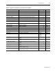
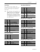
Table 4.14 Snapshot Log Parameters for the Power Block
Parameter Description Range Default
Phase 1 Power Power of phase 1 signed to show direction.
0 to 999.9x10
22
Watts
Phase 2 Power Power of phase 2 signed to show direction.
0 to 999.9x10
22
Watts
Phase 3 Power Power of phase 3 signed to show direction.
0 to 999.9x10
22
Watts
3-Phase Total Power Total power of phase 1, 2, and 3 signed to show direction.
0 to 999.9x10
22
Watts
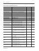
Phase 1 Reactive Power Reactive power of phase 1 signed to show direction.
0 to 999.9x10
22
Vars
Phase 2 Reactive Power Reactive power of phase 2 signed to show direction.
0 to 999.9x10
22
Vars
Phase 3 Reactive Power Reactive power of phase 3 signed to show direction.
0 to 999.9x10
22
Vars
3-Phase Total Reactive Power Total reactive power of phases 1 to 3 signed to show direction.
0 to 999.9x10
22
Vars
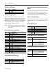
Phase 1 Apparent Power Apparent power of phase 1.
0 to 999.9x10
22
VA
Phase 2 Apparent Power Apparent power of phase 2.
0 to 999.9x10
22
VA
Phase 3 Apparent Power Apparent power of phase 3.
0 to 999.9x10
22
VA
3-Phase Total Apparent Power Total apparent power of phase 1, 2, and 3.
0 to 999.9x10
22
VA
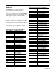
Phase 1 True Power Factor The ratio between the power and apparent power for phase 1;
this value is signed to show lead (+) or lag (-).
-100 to 100 Percent
Phase 2 True Power Factor The ratio between the power and apparent power for phase 2;
this value is signed to show lead (+) or lag (-).
-100 to 100 Percent
Phase 3 True Power Factor The ratio between the power and apparent power for phase 3;
this value is signed to show lead (+) or lag (-).
-100 to 100 Percent
Total True Power Factor The ratio between the power and apparent power for phase 1,
2, and 3; this value is signed to show lead (+) or lag (-).
-100 to 100 Percent
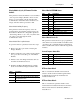
Phase 1 Distortion Power Factor The ratio between the magnitude of the fundamental and the
sum of the magnitudes for all of the current harmonics for
phase 1.
(1)
0 to 100 Percent
Phase 2 Distortion Power Factor The ratio between the magnitude of the fundamental and the
sum of the magnitudes for all of the current harmonics for
phase 2.
1
0 to 100 Percent
Phase 3 Distortion Power Factor The ratio between the magnitude of the fundamental and the
sum of the magnitudes for all of the current harmonics for
phase 3.
1
0 to 100 Percent
Total Distortion Power Factor The ratio between the magnitude of the fundamental and the
sum of the magnitudes for all of the current harmonics for
phase 1, 2, and 3.
1
0 to 100 Percent
Phase 1 Displacement Power
Factor
The cosine of the difference between the phase angle of the
fundamental voltage and current for phase 1; this value is
signed to show lead (+) or lag (-).
1
-100 to 100 Percent
Phase 2 Displacement Power
Factor
The cosine of the difference between the phase angle of the
fundamental voltage and current for phase 2; this value is
signed to show lead (+) or lag (-).
1
-100 to 100 Percent
Phase 3 Displacement Power
Factor
The cosine of the difference between the phase angle of the
fundamental voltage and current for phase 3; this value is
signed to show lead (+) or lag (-).
1
-100 to 100 Percent
Total Displacement Power Factor The cosine of the difference between the phase angle of the
fundamental voltage and current for phase 1, 2, and 3; this
value is signed to show lead (+) or lag (-).
1
-100 to 100 Percent
(1) This value has the same update rate as the harmonic analysis.