
Instruction Sheet User guide

4-6 General Operation
1403-IN001A-US-P
Configuration Items
General
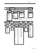
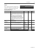
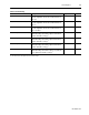
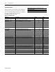
Table 4.1 displays the General Configuration items
for Powermonitor II. The gray scale indicates which
parameters are configured by the Display Module,
the Smart Communication Card, or both.
Display Module and Smart Communication Card
Display Module Only
Smart Communication Card Only
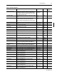
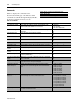
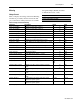
Table 4.1 General Configuration
Parameter Description Range Default User
Setting
New Password Used to change the password needed for modifying
parameter values. A (-1) when using the Smart
Communication Card indicates no change to the
password.
-1 to 9999 0000
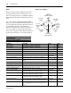
Voltage Mode Determines the system wiring configuration. When in
Demo mode, internal values are displayed for training
purposes.
See Chapter 2 for Wiring Diagrams.
0 = Demo
1 = Single Phase
2 = Open Delta
3 = Delta
4 = Wye
4 = Wye
Filter Mode
(1)
Used for setting up the update rate. Set at 1 for fast update
rates (28 msec nominal), and set at 3 for slower update
rates (90 msec nominal) with high accuracy when
harmonics are present.
1 to 3 2
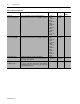
PT Primary The first value for the PT ratio (xxx: xxx) indicating the
voltage at the high end of the transformer.
1 to 10,000,000 120
PT Secondary The second value for the PT ratio (xxx: xxx) indicating the
voltage at the low end of the transformer. For systems with
greater than 120 volts applied to the voltage inputs, the PT
secondary must be configured to greater than 137 volts to
switch to high voltage mode. Example: A 600 V
L-L
(347 V
L-N
)
direct-connect system would be configured with a PT ratio
of 347:347.
1 to 999 120
CT Primary The first value for the PT ratio (xxx: xxx) indicating the
current at the high end of the transformer.
1 to 10,000,000 5
CT Secondary The second value for the PT ratio (xxx: xxx) indicating the
current at the low end of the transformer.
1 to 999 5
Vaux Primary The first value for the Vaux ratio (xxx: xxx) indicating the
voltage at the high end of the transformer.
1 to 10,000,000 1
Vaux Secondary The second value for the Vaux ratio (xxx: xxx) indicating
the voltage at the low end of the transformer.
1 to 999 1
I4 Primary The first value for the PT ratio (xxx: xxx) indicating the
current at the high end of the transformer.
1 to 10,000,000 5
I4 Secondary The second value for the PT ratio (xxx: xxx) indicating the
current at the low end of the transformer.
1 to 999 5
Vaux Volt Mode Determines whether an AC or DC signal is measured by
Vaux.
0 = AC
1 = DC
0 = AC
Snapshot Period Hours The hourly interval in which the snapshot log is updated. 0 to 32766 0
Snapshot Period Minutes The minutely interval in which the snapshot log is updated. 0 to 99 0
Snapshot Period Seconds The secondly interval in which the snapshot log is
updated.
0 to 99 0