Instruction Sheet Bulletin 1403 Powermonitor II (Cat. No. 1403-MM, 1403-LM, 1403-DM) Cat. No. 1403-DM Cat. No.
Important User Information Solid-state equipment has operational characteristics differing from those of electromechanical equipment. Safety Guidelines for the Application, Installation, and Maintenance of Solid-state Controllers (Publication SGI-1.1) describes some important differences between solid-state equipment and hard-wired electromechanical devices.
Table of Contents Using This Instruction Sheet Preface What This Instruction Sheet Contains . . . . . . . . . . . . . . . . . . . . . . . . . . . P-1 For More Information on Additional Power Quality Products . . . . . . . . P-1 Terms and Conventions . . . . . . . . . . . . . . . . . . . . . . . . . . . . . . . . . . . . . . P-2 Product Description Chapter 1 Chapter Objectives . . . . . . . . . . . . . . . . . . . . . . . . . . . . . . . . . . . . . . . . . Introduction . . . . . . . . . . . . . . . . . .
ii Maintenance Chapter 3 Battery Installation and Replacement Procedures . . . . . . . . . . . . . . . . . . Installation . . . . . . . . . . . . . . . . . . . . . . . . . . . . . . . . . . . . . . . . . . . . . Removal . . . . . . . . . . . . . . . . . . . . . . . . . . . . . . . . . . . . . . . . . . . . . . . Disposal of Discharged Lithium Batteries. . . . . . . . . . . . . . . . . . . . . Calibration . . . . . . . . . . . . . . . . . . . . . . . . . . . . . . . . . . . . . . . . . . . . . . . .
iii Master Module Data Acquisition Status . . . . . . . . . . . . . . . . . . . . . Master Module Watchdog Timer Status . . . . . . . . . . . . . . . . . . . . . Real Time Clock Status. . . . . . . . . . . . . . . . . . . . . . . . . . . . . . . . . . Battery Usage Timer Value. . . . . . . . . . . . . . . . . . . . . . . . . . . . . . . Smart Communication Card Status. . . . . . . . . . . . . . . . . . . . . . . . . Smart Communication Card Type . . . . . . . . . . . . . . . . . . . . . . . . .
iv 1403-IN001A-US-P
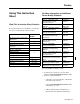
Preface Using This Instruction Sheet What This Instruction Sheet Contains Review the table below to familiarize yourself with the topics contained in this instruction sheet.
P-2 Using This Instruction Sheet Terms and Conventions In this manual, the following terms and conventions are used: Abbreviation AWG BTR BTW CF CSA CT DM EEPROM EMI ID IEC I/O LED LSM MM NEMA PLC PT RAM RFI R I/O RMS ROM SLC SPDT UL VA VAR Term American Wire Gage Block Transfer Read Block Transfer Write Cable Fiber Canadian Standards Association Current Transformer Display Module Electrically Erasable Programmable ROM Electromagnetic Interference Identification International Electrotechnical Commissio
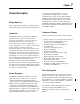
Chapter Product Description Chapter Objectives After completing this chapter, you should be able to identify the product features and system applications. Introduction The Bulletin 1403, Powermonitor II, is uniquely designed and developed to meet the needs of producers and consumers of electric power. The Powermonitor II is a microprocessor based monitoring and control device well suited for a variety of applications.
1-2 Product Description Quick Start - Minimum Device Configuration At a minimum, the following steps MUST be followed for proper operation of your Powermonitor II. Any other device configuration options are only required for operation of additional functions of the Powermonitor II. 1. Configure the PT and CT ratios to match your system.
Product Description 1-3 Communications Setup/Monitoring Software Both versions of the Powermonitor II can use the 1403-NSC Smart Communications Card for communications via Allen-Bradley Remote I/O, RS232 or RS-485, the 1403-NENET card for communications via Ethernet, or the 1403-NDNET card for communications via DeviceNet. Refer to Publication 1403-5.1 Smart Communications Card Instruction Sheet, Publication 1403-5.3 Ethernet Communications Card Instruction Sheet, or Publication 1403-5.
1-4 Product Description Data Logging Both types of oscillography can be triggered manually or as the result of a setpoint. All channels are continuously sampled at a 10.8 kHz sample rate. The Powermonitor II provides three data logs: the Event log, the Min/Max log, and the Snapshot log. Each record of the three logs is date and time stamped to the nearest hundredth of a second.
Chapter Installation Prevent Electrostatic Discharge ! ATTENTION: Electrostatic discharge can damage integrated circuits or semiconductors if you touch backplane connector pins. Follow these guidelines when you handle the module. • Touch a grounded object to discharge static potential. • Wear an approved wrist-strap grounding device. • Do not touch the backplane connector or connector pins. • Do not touch circuit components inside the module. • If available, use a static-safe work station.
2-2 Installation Figure 2.1 Bulletin 1403-XMXX ! ATTENTION: Failure to comply with these mounting requirements may cause damage to the Display Module or compromise the IP65 [NEMA/UL 508, Type 4X (Indoor)] degree of protection per International Standard IEC 529. Cat. No. 1403-xMXXA 120/240 AC 50/60 HZ 125/250 DC Cat. No. 1403-xMXXB 24 AC 50/60 HZ 12/24 DC S1 V1 Wiring of Master Module Terminal Blocks Wire Sizes and Screw Torques Observe all wire lug sizes and screw torques.
Installation Use instrument accuracy PTs when the voltage levels being measured exceed the voltage input ratings. The PT accuracy rating directly affects the system accuracy. For maximum accuracy, the PT used must provide linearity across the voltage range and must introduce a minimal phase angle shift. Note: Remember, for systes with greater than 120 volts applied to the voltage inputs, the PT secondary must be configured to greater than 137 volts to switch to high voltage mode.
2-4 Installation Figure 2.
Installation 2-5 Figure 2.
2-6 Installation Figure 2.
Installation 2-7 Figure 2.
2-8 Installation Figure 2.
Installation 2-9 Figure 2.
2-10 Installation Figure 2.
Installation 2-11 Figure 2.
2-12 Installation Figure 2.
Installation 2-13 Figure 2.11 3-phase 3-wire Grounded L2(B) Phase Open Delta Direct Connect with Three CTs Wiring Diagram LINE L1 Voltage Mode = Open Delta L3 Distribution Ground S1 V1 Fuse S2 Status Inputs V2 V3 Fuse Line-to-Line Voltage must not exceed 347V (otherwise, step down transformers are required).
2-14 Installation Figure 2.
Installation 2-15 Figure 2.
2-16 Installation Figure 2.14 Control Relay Connections Analog Input This input is intended to accept input signals of zero to one volt AC, 50/60 Hz, rms or plus/minus (±) 1.4 VDC. S1 V1 V2 Use twisted pair or shielded pair cable to reduce the level of noise that may be induced on this low level signal. Do not use ground as a return path. A Ground Potential Rise will add to or subtract from the input signal level and affect the reading. V3 S2 Fiber Rx Fiber Tx I3+ Table 2.
Installation LED Indicators Table 2.3 Status Input Parameter Applied resistance verses status state Condition 1 Condition 2 3.5K Ohms or less 5.5K Ohms or = ON greater = Off Isolation Voltage 2500V status input to case 2500V status input to internal digital circuitry Figure 2.15 Status Inputs S1 V1 V3 Voltage Inputs Fiber Tx L/+ N/± PM-II Master Module GRD Ain Analog Input I2+ I2± Acom R14 Current Inputs R11 I3± I4± Figure 2.
2-18 Installation Wiring of Display Module L1/+ L1/Local Frame Ground component of the next unit and repeated for each additional module until the ring is completed. Figure 2.17 shows a typical layout of the fiber optic cabling between one Master Module and three Display Modules. Fiber optic cable assembly specifications are given in Table 2.5 on page 2-18. Important: Always maintain furnished rubber plugs in the transmitter and receiver when cable end connectors are not in place.
Installation Fiber Optic Cable Assembly Strain Relief A strain relief feature at the rear of the Display Module and a wire tie are provided for securing the fiber optic transmit and receive cable assemblies. Use the strain relief feature to protect the fiber optic connections at the rear of the Display Module. Coil each fiber optic cable into an approximately one inch diameter loop and secure each loop to the rear of the Display Module with the wire tie provided per Figure 2.18, Figure 2.19, and Figure 2.
2-20 Installation Communication Connections The Powermonitor II Master Module uses a communications connector for all Communications Cards. This Communications Card connector allows different communication card types to be used to provide the appropriate protocol for a specific system. For example, Cat. No. 1403-NSC is used for Allen-Bradley DF-1 serial and R I/O communications. (Refer to Publication 1403-5.1, Smart Communications Card Instruction Sheet for specific communication information.) Cat. No.
Chapter Maintenance 3 Figure 3.1 Battery Extractor Extended for Battery Installation Battery Installation and Replacement Procedures Installation ! ATTENTION: This procedure may be conducted with full electrical power applied to the Master Module. Use extreme caution when installing the lithium battery into your Bulletin 1403 Master Module. Failure to use extreme caution can lead to personal injury or death, property damage, or economic loss.
3-2 Maintenance Figure 3.2 Master Module with Battery Installed Removal ! ATTENTION: When installing or removing the battery within the Bulletin 1403 Master Module, take care not to come into contact with metallic surfaces if power is applied. 1. Remove the closure plate on the top face of the Master Module with extreme caution per Figure 3.1. Electrical power is normally connected to the Master Module. 2.
Maintenance ATTENTION: The battery is held under pressure within its holder and may be forcefully ejected upon extraction. ! 4. Refer to Battery Installation and Replacement Procedures on page 3-1 for installation of a new battery. 5. Reinstall the access cover plate on the top face of the Master Module. Disposal of Discharged Lithium Batteries In the United States, transportation of depleted lithium batteries for disposal is controlled by the Code of Federal Regulations, Title 49.
3-4 Maintenance 1403-IN001A-US-P
Chapter General Operation 4 Powermonitor II is password protected, and only one entity can modify a Powermonitor II; an entity includes one of the three possible Display Modules or the Smart Communication Card. When a user is in Program Mode, a flashing “P” is displayed at the bottom right-hand corner of the Display Module. General Functionality The Display Module acts as a simple terminal that allows a user to easily view metering parameters or change configuration items.
4-2 General Operation Note: For additional information on measured parameters listed in Chapter 4, refer to Publication 1403-1.0.2, Bulleting 1403 Powermonitor II Tutorial. New Password? 1234 P Editing a Digital Parameter 1. Using the Display Module keys, move into Program mode and display the parameter to be modified. Notice the flashing “P” in the lower right-hand corner. New Password? 0000 P 4.
General Operation 4-3 Issuing a Command 1. Using the four Display Module keys, move into Program mode and display the command to be issued. Notice the flashing “P” in the lower righthand corner. Force Relay 1 { or } P Force Relay 1 Energize P 4. After the desired parameter value is displayed, press the Enter key to execute the command. The selection prompt will reappear and the Display Module is set back to Program mode.
4-4 General Operation Figure 4.
General Operation Program Configuration Program Setpoints P 4-5 P Level 3 Configuration General P Configuration Communication New Password P Voltage Mode Filter Mode① Enable THD② PT & CT Ratio Vaux & I4 Ratio Vaux Volt Mode Snapshot Period Snapshot Buffer Log Status Inp Date Format Time/Date Max Isc① Max Dmnd Load 1① Phase Label Aux Volt Label P RIO Rack Address P RIO Group Number RIO Last Rack RIO Baud Rate Serial Delay Serial Mode RS-232/RS-485 Baud Rate RS-485 Address Note: K-factor V / I① Cr
4-6 General Operation Configuration Items parameters are configured by the Display Module, the Smart Communication Card, or both. General Table 4.1 displays the General Configuration items for Powermonitor II. The gray scale indicates which Display Module and Smart Communication Card Display Module Only Smart Communication Card Only Table 4.1 General Configuration Parameter Description Range Default New Password Used to change the password needed for modifying parameter values.
General Operation 4-7 Table 4.1 General Configuration Parameter Description Range Default Snapshot Buffer Type 0 = Fill and Stop 1 = Circular 1 = Circular 0 = No 1 = Yes 0 = No 1 = Yes 0 = No Date: Year The buffer type used by the snapshot log. Fill and Stop stops filling the buffer when it is full or until the buffer is reset. Circular continuously fills the buffer and overwrites old data when the buffer is full. Enables logging to the event log any activity of the 4 status inputs.
4-8 General Operation Table 4.1 General Configuration Parameter Description Channel A 12-Cycle Oscillograph¨ Used to select which of the seven input channels is 1 = Phase 1 captured for channel A when an oscillograph is triggered. Voltage 2 = Phase 1 Current 3 = Phase 2 Voltage 4 = Phase 2 Current 5 = Phase 3 Voltage 6 = Phase 3 Current 7 = Phase 4 Current Used to select which of the seven input channels is 1 = Phase 1 captured for channel B when an oscillograph is triggered.
General Operation 4-9 Demand Table 4.2 displays the Demand Configuration items for Powermonitor II. The gray scale indicates which parameters are configured by the Display Module, the Smart Communication Card, or both. Display Module and Smart Communication Card Display Module Only Smart Communication Card Only Table 4.2 Demand Configuration Parameter Description Range Default Demand Period Length Specifies the desired period for demand measurement.
4-10 General Operation Commands Table 4.3 displays the commands for the Powermonitor II. The gray scale indicates which commands are available through the Display Module, the Smart Communication Card, or both. Display Module and Smart Communication Card Display Module Only Smart Communication Card Only Table 4.3 Commands Parameter Force Relay #1 and #2 Description Forces Relay #1 and #2 to a known state in which the relay remains at that state until the force is removed.
General Operation Metering 4-11 through the Display Module, the Smart Communication Card, or both. Voltage/Current Table 4.4 displays the Voltage and Current Metering information provided by the Powermonitor II. The gray scale indicates which parameters are available Display Module and Smart Communication Card Display Module Only Smart Communication Card Only Table 4.4 Voltage and Current Metering Parameter Phase 1 L-N Voltage Description RMS line to neutral voltage of phase 1.
4-12 General Operation Power Figure 4.3 Power Metering Table 4.5 displays the Power Metering information provided by the Powermonitor II. The gray scale indicates which parameters are available through the Display Module, the Smart Communication Card, or both. The power quantities (kW, kWH, kVAR, kVARH, and power factor) measured by the Powermonitor II are four-quadrant measurements.
General Operation 4-13 Table 4.5 Power Metering Parameter Phase 2 Distortion Power Factor Description The ratio between the magnitude of the fundamental and the sum of the magnitudes for all of the current harmonics for phase 2.(2) Phase 3 Distortion Power Factor The ratio between the magnitude of the fundamental and the sum of the magnitudes for all of the current harmonics for phase 3.
4-14 General Operation Cumulative Power Table 4.6 displays the Cumulative Power Metering information provided by the Powermonitor II. The gray scale indicates which parameters are available through the Display Module, the Smart Communication Card, or both. Display Module and Smart Communication Card Display Module Only Smart Communication Card Only Table 4.6 Cumulative Power Parameter Kilo-Watt Hours Forward Description The total forward (+) power consumed. Range 0 to 1.
General Operation 4-15 Harmonic Analysis Table 4.7 displays the Harmonic Analysis information provided by the Powermonitor II. The gray scale indicates which parameters are available through the Display Module, the Smart Communication Card, or both. Display Module and Smart Communication Card Display Module Only Smart Communication Card Only Table 4.
4-16 General Operation Setpoints Over Forward Setpoint Theory of Setpoint Operation The Powermonitor II is capable of monitoring many parameters (simultaneously), generating alarms, controlling relays, and triggering other internal actions. Setpoints are used to perform this function. The Powermonitor II supports 20 simultaneous setpoints. A setpoint consists of eight parameters: setpoint number, type, evaluation condition, high limit, low limit, action delay, release delay, and action type.
General Operation Over Reverse Setpoint An over reverse setpoint is the same as an over forward setpoint, except the magnitude of the parameter being monitored must go over the “Setpoint High Limit” in the negative direction. When the magnitude of the parameter being monitored goes over the “Setpoint High Limit” in the negative direction (and stays over the limit) for a 4-17 period of time greater than the “Setpoint Action Delay,” the setpoint becomes active.
4-18 General Operation Under Forward Setpoint An under forward setpoint is the same as an over forward setpoint, except the “Setpoint High Limit” and the “Setpoint Low Limit” are reversed. When the magnitude of the parameter being monitored falls below the “Setpoint Low Limit” in the positive direction (and stays below the limit) for a period of time greater than the “Setpoint Action Delay,” the setpoint becomes active.
General Operation Under Reverse Setpoint An under reverse setpoint is the same as an under forward setpoint, except the magnitude of the parameter being monitored must fall below the “Setpoint Low Limit” in the negative direction. When the magnitude of the parameter being monitored falls below the “Setpoint Low Limit” in the negative direction (and stays below the limit) for 4-19 a period of time greater than the “Setpoint Action Delay,” the setpoint becomes active.
4-20 General Operation Table 4.8 Setpoint Configuration Parameter Name Setpoint Number Setpoint Type Setpoint Evaluation Condition Setpoint High Limit Setpoint Low Limit Setpoint Action Delay Setpoint Release Delay Setpoint Action Type 1403-IN001A-US-P Parameter Description The number of the setpoint being configured. The parameter value to be evaluated by the setpoint. The operator used to evaluate the parameter value.
General Operation 4-21 Table 4.9 Setpoint Type Table 4.
4-22 General Operation Examples of Setpoint Operation Setpoint Example 4 - Under kW Reverse (-) Setpoint Example 1 - Over kW Forward (+) If it is desired that setpoint 1 energizes relay 1 when kW is below -100kW for more than one second, and de-energizes relay 1 when kW exceeds -150kW for more than two seconds, the following settings should be used.
General Operation Data Logging Table 4.11 Event Codes Event Type The Powermonitor II provides three data logs: • Event log • Snapshot log • Min/Max log Each record of the three logs is date and timestamped to the nearest one hundredth of a second. All of the records are stored in battery powered nonvolatile RAM. The data logs remain in memory as long as power is applied to the Master Module or the battery has a usable charge.
4-24 General Operation Table 4.
General Operation 4-25 Table 4.13 Snapshot Log Parameters for the Voltage and Current Block Parameter Phase 1 L-N Voltage Description RMS line to neutral voltage of phase 1. Range 0 to 999.9x10 Default Volts Phase 2 L-N Voltage RMS line to neutral voltage of phase 2. 0 to 999.9x10²² Volts Phase 3 L-N Voltage RMS line to neutral voltage of phase 3. 0 to 999.9x10²² Volts 3-Phase Average L-N Voltage Average RMS voltage of phase 1, 2, and 3. 0 to 999.
4-26 General Operation Table 4.14 Snapshot Log Parameters for the Power Block Parameter Phase 1 Power Description Power of phase 1 signed to show direction. Range 0 to 999.9x10 Default Watts Phase 2 Power Power of phase 2 signed to show direction. 0 to 999.9x10²² Watts Phase 3 Power Power of phase 3 signed to show direction. 0 to 999.9x10²² Watts 3-Phase Total Power Total power of phase 1, 2, and 3 signed to show direction. 0 to 999.
General Operation Table 4.15 The Parameter Listing for the Min/Max Log Min/Max Log The Min/Max log records the minimum and maximum values for 84 parameters. These parameters are listed in Table 4.15. The parameter values are continuously monitored until the Min/Max log is cleared or when the log is disabled. The Min/ Max log can be disabled to make the real time metering update approximately 10 ms faster. The Min/Max log can be displayed using the Display Module or via the Smart Communication Card.
4-28 General Operation Table 4.
General Operation Overall Status 4-29 Master Module NVRAM Status The overall status word is a summary of the individual self-test summary status bits. This allows the user to check a single word to determine the device status. Note: The overall status word is logged in the event log when a self-test is not successful and the OK LED of the product is not illuminated.
4-30 General Operation Real Time Clock Status Bits bit 0 bits 1-15 Hex 0001h Description Summary status Reserved for factory use Battery Usage Timer Value This value indicates the number of days that the Powermonitor II Master Module has been in Battery Backup mode. The timer only increments when the Master Module is without control power. The timer is not automatically cleared and must be manually cleared when the battery is changed.
General Operation Display Module # 1, #2, #3 Firmware Revision Number This parameter returns the firmware revision number of the respective Display Module connected to the fiber loop. It is available only through the Smart Communication Card. This value is returned as an integer such that 1.00 is represented as 100.
4-32 General Operation 1403-IN001A-US-P
Appendix A Catalog Number Explanation Master Module/Limited Metering Master Module 1403 - MM 01 A Bulletin Number 1403 = Power Monitoring, Protection, and Management Products Type of Device MM = Master Module LM = Limited Metering Master Module Current Inputs Power Supply 01 = 1 Amp 05 = 5 Amps A = 120V/240V AC 50/60 Hz or 125V/250V DC B = 24V AC 50/60 Hz or 24/ 48V DC Display Module 1403 - DM Bulletin Number 1403 = Power Monitoring, Protection, and Management Products Type of Device DM = Di
A-2 Catalog Number Explanation Communications Cards/Peripherals/Software 1403 - NSC Bulletin Number 1403 = Power Monitoring, Protection, and Management Products Type of Device NSC = Plug-in Communications Card for Bulletin 1403-MM Devices (RS-232C/RS-485/Allen-Bradley R I/O Protocols) NENET = Plug-in Communications Card for Ethernet NDNET = Plug-in Communications Card for DeviceNet Fiber Optic Accessories 1403 - CF000 Bulletin Number 1403 = Power Monitoring, Protection, and Management Products 1403-I
Appendix B Mechanical Dimensions Figure B.
B-2 Mechanical Dimensions Figure B.
Mechanical Dimensions B-3 Figure B.3 Display Module Mounting Figure B.
B-4 Mechanical Dimensions Figure B.
Variable Content TTL:Chap Is Linked To HD:Running ±1
Variable Content TTL:Chap Is Linked To HD:Running ±3
Appendix Technical Specifications Product Approvals UL 508 listed, File E96956, for Industrial Control Equipment and CSA C22.2 Certified. CE Certification If this product bears the CE marking, it is approved for installation within the European Union and EEA regions. It has been designed and to meet the following directives.
C-2 Technical Specifications Measurement Accuracy, Resolution, and Range See table below for the rating of each parameter. Parameter Volts: V1, V2, V3 Current I1, I2, I3, I4 Accuracy in Percent of Full Scale @ 25° C 50/60 Hz(1) (2) 1403-MM 1403-LM ±0.05% ±0.1% ±0.05% ±0.1% Range (3) (Scale) Nominal Value(3) 10 to 115% of nominal 120VL-N/208VL-L & 347VL-N/600VL-L 1 to 140% of nominal 1A(5) Internal Resolution 1403-MM 0.025% 0.025% 1403-LM 0.05% 0.05% Frequency: ±0.005 Hz ±0.005 Hz 0.
Technical Specifications General Input, Output, and Environmental Ratings Input and Output Ratings 120V/240V AC 50/60 Hz or 125V/250V DC (0.2 Amp maximum loading) 1403-xMxxB 24V AC 50/60 Hz or 24V/48V DC (1 Amp maximum loading) 1403-DMA 120V/240V AC 50/60 Hz or 125V/250V DC (0.05 Amp maximum loading) 1403-DMB 12V/24V AC 50/60 Hz or 12V/24V/48V DC (0.
C-4 Technical Specifications 1403-IN001A-US-P
Appendix Glossary D C capacitor A A unit of electrical current or rate of flow of electrons. One volt across one ohm of resistance causes a current flow of one ampere. A flow of one coulomb per second equals one A device consisting essentially of two conducting surfaces separated by an insulating material or dielectric. A capacitor stores electrical energy, blocks the flow of direct current, and permits the flow of alternating current to a degree dependent upon the capacitance and frequency.
D-2 Glossary demand interval initiator pulses Demand charges are based on peak demand over a utility specified time interval, not on the instantaneous demand (or connected load) at any given moment. Typical demand intervals are 15, 20 and 30 minutes. Electrical impulses generated by pulse-initiator mechanisms installed in utility revenue meters. Each pulse indicates the consumption of a specific number of watts. These pulses can be used to measure energy consumption and demand.
Glossary D-3 O power factor correction ohm Steps taken to raise the power factor by closely aligning the current to be in phase with the applied voltage. Most frequently this consists of added capacitance to increase the lagging power factor of inductive circuits. The unit of electrical resistance. One ohm is the value of resistance through which a potential difference of one volt will maintain a current flow of one ampere.
D-4 Glossary resistance volt-ampere demand The property of a substance which impedes current flow and results in the dissipation of power in the form of heat. The unit of resistance is the ohm. One ohm is the resistance through which a difference of potential of one volt will produce a current of one ampere. Where peak average demand is measured in voltamperes rather than watts. The average VA during a predefined interval. The highest average, i.e. Peak VA demand, is sometimes used for billing.
Index B battery replacement 3-1 disposal 3-3 installation 3-1 removal 3-2 C calibration 3-3 catalog number explanation A-1 cleaning instructions 3-3 commands 4-10 communication connections 2-20 communications 1-3 configuration items 4-6 demand 4-9 general 4-6 control power 2-2 D data logging 4-23 event log 4-23 min/max log 4-27 snapshot log 4-24 description 1-1 device configuration 1-1 dimensions B-1 display module B-2 display module cutout B-3 display module into the protective enclosure B-4 display module
I-2 general purpose status bits 4-31 master module auxiliary frequency 4-31 master module data acquisition status 4-29 master module device ID 4-31 master module EEPROM status 4-31 master module fiber loop back status 4-31 master module firmware revision number 4-28 master module NVRAM status 4-29 master module power supply status 4-29 master module RAM status 4-29 master module ROM status 4-29 master module watchdog timer status 4-29 number of display modules 4-30 options bit field 4-28 overall status 4-2
I-3 1403-IN001A-US-P
Back Cover Publication 1403-IN001A-US-P - August 1999 Supersedes Publication 1403-5.0 November 1997 and Publication 1403-5.0-DU3 August 1998 PN 40055-161-02(B) © (1999) Rockwell International Corporation. Printed in the U.S.A.