ALLEN-BRADLEY Allen-Bradley Line Synchronization Module (Bulletin 1402 LSM) Installation and Operation Manual
Important User Information Solid state equipment has operational characteristics differing from those of electromechanical equipment. “Safety Guidelines for the Application, Installation and Maintenance of Solid State Controls” (Publication SGI-1.1) describes some important differences between solid state equipment and hard–wired electromechanical devices.
Table of Contents Product Description . . . . . . . . . . . . . . . . . . . . . . . . . . Chapter Objectives . . . . . . . . . . . . . . . . . . . . . . . . . . . . . . Introduction . . . . . . . . . . . . . . . . . . . . . . . . . . . . . . . . . . . General Description . . . . . . . . . . . . . . . . . . . . . . . . . . . . . Synchronization and Load Share Errors . . . . . . . . . . . . . . Measurements . . . . . . . . . . . . . . . . . . . . . . . . . . . . . . . . . . Module Configuration . . . . . . .
Table of Contents ii PLC Interface . . . . . . . . . . . . . . . . . . . . . . . . . . . . . . . . . . Discrete I/O Interface . . . . . . . . . . . . . . . . . . . . . . . . . Discrete Outputs (From the PLC Processor) . . . . Discrete Inputs (To the PLC Processor) . . . . . . . . Block Transfer Data Interface . . . . . . . . . . . . . . . . . . . Configuration Software Support . . . . . . . . . . . . . . . . . 6200 Software . . . . . . . . . . . . . . . . . . . . . . . . . . . .
Preface A–B Using This Manual What This Manual Contains Review the table below to familiarize yourself with the topics contained in this manual.
Preface Using This Manual Terms and Conventions ii In this manual, the following terms and conventions are used: Abbreviation Term AWG American Wire Gage BTR Block Transfer Read BTW Block Transfer Write CT Current Transformer EEPROM Electrically Erasable Programmable ROM EMI Electromagnetic Interference ID Identification LED Light Emitting Diode I/O Inputs and Outputs should be considered with respect to the PLC processor LSM Line Synchronization Module PT Potential Transformer RA
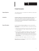
Chapter A–B 1 Product Description Chapter Objectives After reading this chapter, you should be able to identify the product features and system applications. Introduction The Bulletin 1402, Line Synchronization Module (LSM), is designed to meet the needs of manufacturers, system integrators, and users of 3 phase alternators and cogeneration systems or for applications that require two three–phase systems to be synchronized with each other.
Chapter 1 Product Description Synchronization and Load Share Errors In order to synchronize two three phase systems without high instantaneous energy transfer, the voltage, frequency, and phase displacement of the two systems must be matched. Kilowatt Load Sharing can be implemented by matching the ratio of power system load to system capacity to the ratio of actual alternator power to rated alternator power.
Chapter 1 Product Description Measurements In addition to the synchronization function, the LSM provides an extensive array of monitoring information for systems wired in Wye, Delta, or Open Delta. The monitored data is shown below: Table 1.
Chapter 1 Product Description 1–4
Chapter A–B 2 Installation Location Enclosure The Bulletin 1402 Line Synchronization Module (LSM) should be installed in a Bulletin 1771 I/O chassis that is located in a dry, dirt free environment away from heat sources and very high electric or magnetic fields. The module is designed to operate in an ambient temperature between 0 and 60° Celsius. The LSM is typically installed in a local rack in order to maximize data transfer rates.
Chapter 2 Installation Swing Arm The LSM requires the use of a Cat. No. 1771-WC (10 position, gold contacts) Swing Arm. Wiring There are two sets of terminals associated with the LSM; a 10 position swingarm and an 8 position fixed terminal block. All customer wiring to the LSM is accomplished via these terminals on the front of the module. The 10–position swingarm is used to make all of the voltage (PT) connections to the module as well as the Load Share connections.
Chapter 2 Installation PT and CT Transformer Selection For proper monitoring and synchronization, correct selection of current transformers (CT’s) and potential transformers (PT’s) is critical. The following paragraphs provide the information required to choose these transformers. Also refer to transformer operational characteristics Pages 3–2 and “Factory Configuration Parameters” listed on Page B–2. PT Selection The LSM is designed for a nominal full scale input voltage of 120V AC.
Chapter 2 Installation Other factors may affect CT accuracy. The length of the CT cabling should be minimized because long cabling could contribute to excessive power load on the CT and inaccuracy. The CT burden rating must exceed the combined burden of the LSM plus cabling plus any other devices connected in the measuring circuit (burden is the amount of load being fed by the CT, measured in Volt–Amps calculated at 5A full scale.).
Chapter 2 Installation PT and CT Wiring Connections Continued Connection for Three Phase Delta, 3 Wire Systems with 3 PT’s & 3 CT’S When configured for ungrounded (floating) Delta operation, the LSM senses the L–L voltages between each of the phases. The “Voltage Mode” of the LSM should be set to “2” (as described in Chapter 3, “General Operation”). Figure 2.3 shown on Page 2–9 provides the wiring diagram for this configuration. Wiring and polarity marks must be exactly as shown for correct operation.
Chapter 2 Installation Current Transformer Connections The LSM is equipped with four CT inputs, designated I1 – I4. Inputs I1 – I3 are used to measure the current in the synchronizing circuit. These inputs are wired as shown on Pages 2–7 through 2–11 in Figure 2.1 through Figure 2.5. Input I4 is optional and is typically used to measure current in the neutral or ground conductor. The primary rating for I4 can be different than the primary rating for transformers I1 – I3.
Chapter 2 Installation Figure 2.
Chapter 2 Installation Figure 2.
Chapter 2 Installation Figure 2.
Chapter 2 Installation Figure 2.
Chapter 2 Installation Figure 2.
Chapter 2 Installation 2–12
Chapter A–B 3 General Operation Chapter Objectives This chapter: • • • Operational Characteristics introduces the user to the controls and operation describes each function defines operating parameters Functional The LSM has six different modes of operation. These modes are described below. Configuration Before the LSM can perform its intended functions, it must be configured by the integrator/OEM or user.
Chapter 3 General Operation Operational Characteristics Continued Voltage Mode This entry is used to indicate if the system being monitored is wired in a WYE, a Delta, or an open Delta. A value of “1” will indicate a WYE system, a value of “2” will indicate a three transformer Delta system, and a value of “4” will indicate a two transformer Open Delta system. Line–to–Neutral values will be provided only when a WYE is configured.
Chapter 3 General Operation Operational Characteristics Continued Phase Match Error Upper and Lower Acceptance Limits These entries are used to specify the upper and lower acceptance limits for matching Synchronizing Bus phasing to the Reference Bus phasing. The value is specified in degrees and must be between 0 and 45. Acceptance Window Delay This entry is used for the delayed acceptance window method of synchronization. The value is specified in steps of 0.05 seconds and must be between 0.00 and 10.
Chapter 3 General Operation Operational Characteristics Continued Demand Period This entry is used to specify the desired period for demand measurement. The value is specified in minutes and must be between 1 and 99. Number Of Demand Periods This entry specifies the number of demand periods that should be averaged to determine the actual demand. The value must be between 1 and 15.
Chapter 3 General Operation Operational Characteristics Continued Synchronization Continued The “Permissive Synchronization” discrete output from the PLC–5 prevents the LSM from issuing any error signals, but it asserts the “Close Breaker” discrete input to the PLC–5 if the synchronization criteria are satisfied.
Chapter 3 General Operation Operational Characteristics Continued Power Monitoring In addition to the synchronization function, the LSM provides an extensive array of monitoring information. This data is accessible through one of several different block transfers. (See Appendix B, “Block Transfer Tables and Discrete I/O Definition”, for additional information.) All voltage and current measurements presented by the LSM are true RMS.
Chapter 3 General Operation Operational Characteristics Continued Load Sharing The load sharing function allows multiple synchronizing buses to split the load requirements on a power system based on the relative capacity of each of the alternators. To use this function, the LSM must be configured with a “Maximum Alternator Output Power” entry, a “Load Share Full–Scale Voltage” entry, a “Load Share Deficit” entry, and a “Load Share Excess” entry.
Chapter 3 General Operation Operational Characteristics Continued Control The user can direct the LSM to perform several different functions by sending the appropriate block transfer data to the “Control Parameters Table”. (See Appendix B, “Block Transfer Tables and Discrete I/O Definition”, for additional information.) The functions that can be initiated are as follows: • • • Execute Self–Test (If the Execute Self–Test option is selected, no other control options will be executed.
Chapter 3 General Operation Operational Characteristics Continued Self–test Continued The red Fault LED flashes while the complete self–test is being performed. The Fault LED will remain on continuously if the self–test fails. The Fault LED will turn off if the self–test is successfully completed. The green Run LED is illuminated during the self–test and then turned off after the test is completed. The Run LED also flashes each time a block transfer is executed.
Chapter 3 General Operation PLC Interface Continued Discrete Outputs (From the PLC Processor) The following discrete output control signals will be provided from the PLC–5 processor via the back plane: • • • • • • • Initiate Synchronization Auto–Synchronization Mode Check Synchronization Mode Permissive Synchronization Mode Load Share Disable Isochronous/Droop Mode Enable Single Phase Synchronization Discrete Inputs (To the PLC Processor) The following discrete input control signals will be provided to
Chapter 3 General Operation PLC Interface Continued Configuration Software Support 6200 Software Setup assistance for the LSM module is provided through the 6200 version 4.4 or later I/O Configuration Software. This configuration software contains the functionality to configure the module and to monitor the data produced by an operating module. To make use of the configuration software, the ladder must exist with block transfer instructions programmed as shown in Appendix C.
Chapter 3 General Operation 3–12
Chapter A–B 4 Application Information Overview Modes of Operation The Line Synchronization Module (LSM) has several modes of operation. Upon successful configuration, or on power up with a previously configured module, the LSM will be in one of the following modes: • • • • Monitor Only Monitor with Load Share Synchronization and Monitor Synchronization and Monitor with Load Share The state of the discrete outputs from the PLC–5 to the LSM controls the mode of operation of the LSM.
Chapter 4 Application Information Overview Continued Synchronization and Monitor with Load Share In this mode of operation, data is returned for Synchronizing Bus voltage, current, and power values, and reference bus voltage values. The error values and discrete inputs to the PLC–5 for synchronization and load share are modified. Interfacing to the LSM Block Transfer Communications The LSM is capable of exchanging large amounts of data with the PLC processor via the Block Transfer mechanism.
Chapter 4 Application Information Interfacing to the LSM Continued Block Transfer Communications Continued For example, the words 10 modulus 103 and 0 modulus 100 would be processed in this manner: (10 * 1000) + 0. The words 10 modulus 100 and 500 modulus 10–3 would be processed in this manner: 10 + (500 /1000). To process numbers to be sent to the LSM in this format, a number greater than 1,000 needs to be divided by 1,000 to obtain the modulus 103 word.
Chapter 4 Application Information Interfacing to the LSM Continued Acquiring Data From the LSM The data from the LSM is returned in four tables. These tables are again differentiated by the size/ID of the BTR instruction. These tables are Synchronizing Bus Error Parameters, Synchronizing Bus Voltage/Current Parameters, Synchronizing Bus Power Parameters, and Reference Bus Voltage Parameters. The sizes and contents of these tables are provided in Appendix B of this document.
Chapter 4 Application Information Interfacing to the LSM Continued Discrete Outputs From The PLC–5 Continued present, the synchronization fails and the “Synchronization Failure” discrete input to the PLC–5 will be asserted. Additional information pertaining to the cause of the failure may be obtained by reading the appropriate block transfer data from the “Synchronizing Bus Error Parameters” table. (See Appendix B, “Block Transfer and Discrete I/O Definition”, for additional information.
Chapter 4 Application Information Interfacing to the LSM Continued Discrete Inputs to the PLC–5 The discrete inputs to the PLC–5 are as follows: Table 4.
Chapter 4 Application Information Interfacing to the LSM Continued Discrete Inputs to the PLC–5 Continued The Lower Speed – Frequency Adjust synchronization error discrete input to the PLC–5 indicates that the Synchronizing Bus is producing voltage at a frequency higher than that of the Reference Bus. The Raise Speed – Phase Adjust synchronization error discrete input to the PLC–5 indicates that the Synchronizing Bus is producing a voltage which is between 0 and 180 degrees behind the Reference Bus.
Chapter 4 Application Information Interfacing to the LSM Continued Discrete Inputs to the PLC–5 Continued The Close Breaker discrete input to the PLC–5 indicates that all synchronization criteria have been met and it is acceptable to close the breaker between the Synchronizing Bus and the Reference Bus. The Synchronization Failure discrete input to the PLC–5 indicates a synchronization error. When this bit is set, the LSM cannot perform Synchronizing Bus / Reference Bus synchronization.
Chapter 4 Application Information Ladder Program Description Continued Data Files Used Table 4.4 Data File Data Description b3/0 Internal Trigger b3/1 Config Mode Enable b3/2 Data Reset b3/3 Run mode Sequence Complete b3/4 Valid Config Data B3 B b3/5 Config Sequence Complete/Data Valid b3/6 Module Config Complete b3/9 One–shot bit b3/10 One–shot bit N10 n10:0 Sequencer output (BT select word) N21 Config mode sequencer input file.
Chapter 4 Application Information Ladder Program Description Continued Data Files Used Continued The following description applies to both files N21 and N22. The data at word 0 of N21 and N22: 1 must be the same. N2x:0 is the reset word for the sequencer and N2x:1 is the first word in the rotation of the sequencer. The data held in file N21 consists of the block transfer numbers needed to complete configuration in the order necessary to perform that task.
Chapter 4 Application Information Ladder Program Description Continued Data Files Used Continued Table 4.
Chapter 4 Application Information 4–12
Appendix A Catalog Number Explanation LINE SYNCHRONIZATION MODULE 1402 - LS 5 1 Bulletin Number 1402 Power Monitoring, Protection, and Management Products Type of Device LS Line Synchronization Module Measured Current 5 5A Full Scale Measured Phase Voltage 1 100/120V AC A–1
Appendix A Catalog Number Explanation A–2
Appendix A–B B Block Transfer and Discrete I/O Definition Table B.
Appendix B Block Transfer and Discrete I/O Definition Table B.
Appendix B Block Transfer and Discrete I/O Definition Table B.2 Factory Configuration Parameters (Continued) Parameter Number Word Number Description Range Modulus 14 23 Maximum Alternator Output Power in Kilowatts 0 – 999 100 24 [Limits 0 – 999,999] 0 – 999 103 25 Load Share Full–Scale Voltage in Volts (Step size 0.01 volts) 0 – 999 10–3 26 [Limits 2 – 4] 2–4 100 16 27 Load Share Excess [ Limits –0.500 – 0] 500 – 0 10–3 17 28 Load Share Deficit [ Limits 0 – 0.
Appendix B Block Transfer and Discrete I/O Definition Table B.
Appendix B Block Transfer and Discrete I/O Definition Table B.
Appendix B Block Transfer and Discrete I/O Definition Table B.
Appendix B Block Transfer and Discrete I/O Definition Table B.6 Synchronizing Bus Error Parameters Parameter Number 1 2 3 Word Number Description 1 V Voltage Match Error in Percent ±0 – 999 10–3 2 (Step Size of 0.05 %) ±0 – 100 100 3 Frequency Match Error in Hz ±0 – 999 10–3 4 (Step Size of 0.
Appendix B Block Transfer and Discrete I/O Definition Table B.
Appendix B Block Transfer and Discrete I/O Definition Table B.
Appendix B Block Transfer and Discrete I/O Definition Table B.
Appendix B Block Transfer and Discrete I/O Definition Table B.
Appendix B Block Transfer and Discrete I/O Definition Table B.
Appendix B Block Transfer and Discrete I/O Definition Table B.
Appendix B Block Transfer and Discrete I/O Definition Table B.
Appendix B Block Transfer and Discrete I/O Definition Table B.
Appendix B Block Transfer and Discrete I/O Definition Table B.11 Diagnostic Parameters (Continued) Parameter Number Word Number Description Range Modulus 18 20 Seconds 0 – 59 100 19 21 Reserved for Product Expansion ––– ––– 20 22 Reserved for Product Expansion ––– ––– 21 23 Reserved for Product Expansion ––– ––– 22 24 Reserved for Product Expansion ––– ––– # Bit value of ”0” indicates test passed Bit value of ”1” indicates that test failed. Table B.
Appendix B Block Transfer and Discrete I/O Definition Table B.
Appendix B Block Transfer and Discrete I/O Definition B–18
Appendix A–B C Sample Ladder Listing This is a sample ladder. It shows a way to configure the block transfers for the 1402–LSM and the Power I/O Configuration software. ! ATTENTION: Proper operation of the ladder program is the responsibility of the user. No warranty is expressed or implied by using this ladder configuration. This ladder is subject to change. Rung 2:0 Assigns an external trigger to set an internal trigger. The timer allows the internal trigger to be set for a prescribed time.
Appendix C Sample Ladder Listing Rung 2:2 When the trigger is present and the run sequence is completed, the config mode is enabled until the Module configuration sequence is completed. Rung 2:2 Rung 2:3 Used to reset the module configuration complete Bit. Rung 2:3 Rung 2:4 Moves word zero into the sequencer output (Block transfer control) on the first pass. If not used the processor may fault.
Appendix C Sample Ladder Listing Rung 2:5 Resets the configuration sequencer to position zero when in the run mode. Rung 2:5 Rung 2:6 Resets the run sequencer to position zero when in the configuration mode. Rung 2:6 Rung 2:7 Ensures that the run sequence is complete. Rung 2:7 Resets configuration mode sequencer when in the run mode.
Appendix C Sample Ladder Listing Rung 2:8 Sequences through block transfers pre–selected by the Data file #N21. The sequencer is triggered when the previous block transfer has completed or failed. The sequence continues until the module has valid data. Rung 2:8 Sequence through pre–selected block transfers when the active block transfer has completed or has encountered an error. The configuration sequence is located in #N21:0. Rung 2:9 Sequences through block transfers pre–selected by the Data file #N22.
Appendix C Sample Ladder Listing Rung 2:11 Performs block transfer read of user configuration parameters. Rung 2:11 Rung 2:12 Performs block transfer read of acknowledge factory configuration parameters. Rung 2:12 Rung 2:13 Performs block transfer read of Acknowledge user configuration parameters. Rung 2:13 Perform BTR User Configuration Parameters. | User | | Sequencer Config.
Appendix C Sample Ladder Listing Rung 2:14 Performs block transfer read of Sync bus error parameters. Rung 2:14 Rung 2:15 Performs block transfer read of Sync bus Voltage/Current parameters. Rung 2:15 Rung 2:16 Performs block transfer read of Sync bus Power parameters. Rung 2:16 C–6 Perform BTR Synchronizing Bus Error Parameters. | Sync.
Appendix C Sample Ladder Listing Rung 2:17 Performs block transfer read of Reference bus Voltage parameters. Rung 2:17 Rung 2:18 Performs block transfer read of Diagnostic parameters. Rung 2:18 Rung 2:19 Performs block transfer write of Factory Configuration parameters. Rung 2:19 Perform BTR Reference Bus Voltage Parameters. | Ref. Bus | | Sequencer Volt.
Appendix C Sample Ladder Listing Rung 2:20 Performs block transfer write of User Configuration parameters. Rung 2:20 Rung 2:21 Used by the 6200 software to perform block transfer write of Control Request.
Appendix C Sample Ladder Listing Rung 23 Configuration data is valid and the configuration sequencer is done. Rung 2:23 Rung 2:24 Configuration is complete and all configuration block transfers successful. Return to run mode. Rung 2:24 Rung 25 End of file. Rung 2:25 Configuration data is valid and the sequence is complete.
Appendix C Sample Ladder Listing C–10
Appendix D Line Synchronization Module Mechanical Dimensions Figure 1 Dimensions for Line Synchronization Module 1.57 ( .06 ) 23.8 ( .94 ) 62.26 31.72 ( 2.45 ) ( 1.25 ) 6.73 ( .27 ) 53.94 (2.12) 254 ( 10.00 ) 126.87 ( 5.00 ) 17.65 ( .70 ) NOTES: 1. Dimensions shown in millimeters (inches). 2. All dimensions are approximate and not intended for manufacturing purposes. 3. Approximate shipping weight 2.72 kg (6.0 Lbs). 148.08 ( 5.
Appendix D Mechanical Dimensions D–2
Appendix A–B E Bulletin 1402 Technical Specifications INPUTS: Current 0 to 5A RMS Cont., 200A RMS 1 Second Frequency 40 to 100 Hz (steady-state) Dielectric Withstand Voltage 2500V RMS Current Input Burden 0.05 VA Voltage 120V RMS (339 Vpk-pk) Maximum Peak Voltage Input Impedance/Burden 728K W/0.02 VA SYNCHRONIZATION WINDOW: Independent Upper & Lower Thresholds Voltage 0.05% steps Frequency 0.01 Hz steps Phase 1 degree steps ISOLATED LOAD SHARING INPUT/OUTPUT: Max.
Appendix E Technical Specifications CSA HAZARDOUS LOCATION APPROVAL CSA certifies products for general use as well as for use in hazardous locations. Actual CSA certification is indicated by the product label as shown in the example below, and not by statements in any user documentation. OPERATING TEMPERATURE CODE T3C CLASS 1, GROUPS A, B, C AND D, DIV.
Appendix E Power Monitoring Approbation d’utilisation dans des emplacements dangereux par la CSA La CSA certifie les produits d’utilisation générale aussi bien que ceux qui s’utilisent dans des emplacements. La certification CSA en vigueur est indiquée par l’étiquette du produit et non par des affirmations dans documentation à l’usage des utilisateurs. OPERATING TEMPERATURE CODE T3C CLASS 1, GROUPS A, B, C AND D, DIV.
Appendix E Technical Specifications Compliance to European Union Directives If this product has the CE mark it is approved for installation within the European Union and EEA regions. It has been designed and tested to meet the following directives.
Notes A–B
Notes
Notes
Notes
Allen-Bradley, a Rockwell Automation Business, has been helping its customers improve productivity and quality for more than 90 years. We design, manufacture and support a broad range of automation products worldwide. They include logic processors, power and motion control devices, operator interfaces, sensors and a variety of software. Rockwell is one of the world’s leading technology companies. Worldwide representation.