
Software Owner's manual


Chapter 3
Installation
3–9
!
ATTENTION: Special high level isolation is required between
units when the possibility of high ground potential differences
exist. This may occur when separate grounds are used, or when
communicating to a unit off of the power ground matt. Failure to
do so can lead to personal injury or death, property damage, or
economic loss.
Important: For each site, total RS–485 cable length (Maximum 4,000–ft.)
between all devices in the RS–485 network when using 22 gauge shielded
twisted pair.
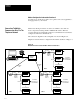
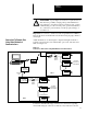
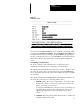
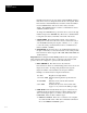
Additional methods of connecting the computer running Powermonitor
Software to Powermonitor sites include fiber optic, radio, and microwave
links. See Figure 3.5.
Figure 3.5
Connection to Remote Sites using Other Methods of Communications
Radio
TX/RX
Site 1
To Feeders,
Transducers, or
Pulse Initiations
RS–232C
RS–485
Powermonitor #1
Powermonitor #2
Powermonitor #32
To Feeders,
Transducers, or
Pulse Initiations
RS–232C
RS–485
Powermonitor #1
Powermonitor #2
Site 2
IBM PC with Hayes Modem
Modem
Fiber Optic
Converter to
RS–232C Output
Fiber Optic
Converter to
RS–232C Output
Fiber Optic
Link
Powermonitor #32
Catalog
Number
1400-CC
Catalog
Number
1400-CC
Contact the Allen–Bradley Support Division for information regarding
remote links using any of the above methods or any methods not shown.
Connection To Remote Sites
Using Other Methods of
Communications