
Software Owner's manual

Chapter 3
Installation
3–6
!
ATTENTION: Before connecting any communications cables,
confirm that the Powermonitor is configured for RS–232C
communications and the computer port has been configured for
RS–232C operation. Refer to Publication 1400–800, ‘‘Bulletin
1400 Powermonitor Installation and Operation Manual,” to
determine correct configuration of the port.
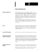
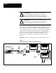
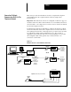
The remote site requires a RS–232C cable between the modem and the serial
port of the Powermonitor. If you wish to assemble the RS–232C cable
yourself, the cable pin assignments are given below. Alternatively,
pre–assembled RS–232C cables can be ordered from Allen–Bradley.
Modem Connector DB–25, pin DCU Card Labeled
2 (Rx)
wire to TXD
3 (Tx) wire to RXD
7 (signal ground) wire to SG
5 (RTS)
wire to RTS
1. Modem DB–25S pin 3 (modem Tx ) goes to device RXD.
2. Modem DB–25S pin 7 (modem GND) goes to device GND.
3. Modem DB–25S pin 4 is jumpered to modem DB–25S pin 5.
4. Modem DB–25S pin 6 is jumpered to modem DB–25S pin 20.
To install the RS–232C cable, connect the DB25 connector end of the
RS–232C cable to the serial port at the back of the modem. The four
conductors at the other end of the cable are then connected to the appropriate
communications points located on the Catalog Number 1400–DCU
communications card. The connections are shown in Figure 3.3 on page 3–5.