
Owner's manual

Installation Instructions
Powermonitor Accessory Kit
Catalog Number
1400-PM-ACC
About the Powermonitor
Accessory Kit
The Powermonitor accessory kit simplifies the installation of a Powermonitor
unit by making all the mandatory installation accessories available in one catalog
number.
All applications require the installation of current transformers for proper power
and energy. Proper current transformer selection is required, based on customer
application. If you have questions, please contact your local Rockwell
Automation office or technical support at
http://www.rockwellautomation.com/support
.
Based on specific customer application, additional potential transformers may be
required. Refer to these publications:
• For the Powermonitor 3000 unit, see the installation instructions,
publication 1404-IN007
, or the user manual, publication 1404-UM001.
• For the Powermonitor 1000 unit, see the installation instructions,
publication 1408-IN001
, or the user manual, publication 1408-UM001.
You can view or download publications at
http://www.rockwellautomation.com/literature
.
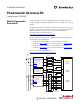
Fuse 10 Amp
Fuse 10 Amp
Fuse 10 Amp
Line
L2 L3L1
Load
Fuse 1 Amp
Powermonitor 1000 / 3000
V1
VN
V3
V2
Voltage
Inputs
L1
L2/N
GND
Control
Power
I1+
I1 -
I2+
I2 -
I3+
I3 -
IN+
IN -
Current
Inputs
Customer
Chassis Ground
Shorting Block
1400-PM-ACC
PT Configuration
To find your specific wiring mode
(Delta, WYE, Open Delta, Direct
Connect) please refer to the
following publications:
Powermmonitor 3000 Unit -
1404-IN007
Powermonitor 1000 Unit -
1408-IN001
Control Power
1 Amp Fuse
We recommend that Control
Power is from a separate source
than the Voltage Inputs.
CT Configuration
To find your specific wiring
mode (Delta, WYE, Open Delta)
please refer to the following
publications:
Powermmonitor 3000 Unit -
1404-IN007
Powermonitor 1000 Unit -
1408-IN001