
Instruction Manual

9
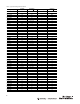
Resistor
Se
l
e
c
t
i
on
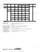
When the
r
e
s
is
tivity
of
the
liquid is
known, convert
to
ohms
•
cm and
s
e
le
c
t
the range resistor that corresponds
to
the
r
e
s
is
tivity
range
in
Tab le
5.
When the
r
e
s
is
tivity
of
the
liquid is
not known, immerse the high
le
v
e
l
probe
tip
1/16 in. (1.5 mm)
into
the
liquid.
For operation
with
the relay energized
with
the probe immersed,
connect
th
e
Range
1
resistor (330 ohms)
to
Termin a l s
1
and
2.
The relay
s
hou
ld
energize.
If it
does not, use successively higher range resistors
until
th
e
relay energizes.
If
relay action
is
sluggish, use the next higher
range
r
e
s
isto
r
.
For operation
with
the relay de-energized
with
the probe immersed,
c
onn
e
c
t
the Range
1
resistor (330 ohms)
to
Termin a l s
1
and
3.
The relay
s
hou
ld
de-energize.
If it
does not, use successively higher range resistors
until
th
e
relay de-energizes.
If
relay action
is
sluggish, use the next higher
r
a
ng
e
r
e
s
isto
r
.
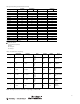
N
o
t
e
:
For
r
e
s
i
s
t
an
c
e
s
e
n
s
i
ng
app
li
c
a
t
i
on
s
,
use the
v
a
l
u
e
s
of
r
e
s
i
s
t
an
c
e
s
e
n
s
i
ng
s
e
n
s
i
tivity
li
s
t
e
d
in
T
ab
l
e
6 in
p
l
a
c
e
of
p
r
ob
e
circuit
r
e
s
i
s
t
i
v
i
t
y
for
s
e
l
e
c
t
i
on
of
the proper r
ang
e
r
e
s
i
s
t
o
r
.
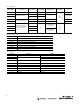
N
o
t
e
:
Wiring for
Ranges 1--2--3
d
i
ff
e
r
s
from
Ranges
4--5--6. F
o
ll
o
w
wiring
i
n
s
t
r
u
c
t
i
on
s
in Wiring D
i
ag
r
a
m
s
in F
i
gu
r
e
s
6--11.
W
i
r
i
ng
All
e
x
te
r
n
a
l
wiring
should
c
on
f
o
r
m
to
the
N
a
tio
n
a
l
Electric Code
a
nd
applicable lo
c
a
l
codes. See
wiring
diagrams
for
e
x
te
r
n
a
l
connections.
W
ir
e
no smaller than 16
AWG is
r
e
c
o
mm
e
nd
e
d.
Since the 13DJ3 c
on
tr
o
l
operates
with
liq
u
id
s
having high
e
le
c
tr
ic
a
l
resistance, the in
s
u
la
tio
n
resistance
of
the
wiring
connecting the c
on
tr
o
l
to
the probe must be extremely high.
It is
important, th
e
r
e
f
o
r
e
,
to
use
p
la
s
tic
insulated
w
ir
e
to
insure that the in
s
u
la
tio
n
will
not absorb
moisture
or
c
r
a
c
k
and permit leakage paths
to
develop. Wires insulated
with
paper,
cotton,
asbestos, etc. must not be used. Series 63 sanitary
probes are
f
u
r
n
is
h
e
d
with
a molded separable connector and
10 ft
(3 m)
cable
a
ss
e
m
b
ly
.
ATTENTION
Do not
run probe
or
reset
l
ea
d
s
in
same
conduit with
power
li
n
e
s
or
h
i
gh
current
c
a
rry
i
ng
c
ondu
c
t
o
r
s
.
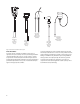
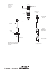
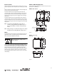
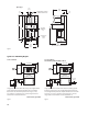
Outline and Mounting
D
i
m
e
n
s
i
on
s
Unless otherwise indicated, dimensions shown are
in
inches. Those
in
parentheses are
in
m
illim
e
te
r
s
.
Figure 3
Figure 4
.188
(4.8)
NEMA 1 #61-3322-3
3.938
(100)
.875 (22.2)
5.25
(133.4)
5.938
(150.8)
7.25
(184.1)
4.875
(123.8)
.375
(9.5)
.688
(17.5)
5.938
(150.8)
.812
(20.6)
3.875
(98.4)
.375
(9.5)
.875 DIA. (22.2)
8 K.0.’S TOTAL
*
*
*
*
TYP.
1.188
(30.2)
1.063
(27)
*
*
NEMA 3, 4, 5, 12 & 13
#61-4090
4
(101.6)
8.75
(222.2)
9.5
(241.3)
.375
(9.5)
6.25
(158.7)
4.875
(123.8)
.625 (15.9)
.312 (7.9)
HOLE (4)
8.25
(209.5)