
Instruction Manual

8
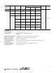
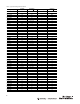
Table 7:
Speed of Response
(
s
e
c
ond
s
)
Ordering Ins
t
r
uc
t
ions
1.
S
e
le
c
t
13DJ3--3000
2.
S
e
le
c
t
C
o
n
t
r
o
l
B
a
s
e
3.
Select
P
r
ob
e
F
i
tt
i
n
g
4.
Select
P
r
ob
e
Rod
A
ss
em
b
li
es
for
61 Series
P
r
ob
e
F
i
tt
i
n
gs
Range
Solid-State Outputs
Relay Output
O
N
O
FF
O
N
O
FF
1
0.0
03
0.0
60
0.0
12
0.0
70
2
0.0
035
0.0
60
0.0
13
0.0
70
3
0.0
04
0.0
60
0.0
14
0.0
70
4
0.0
06
0.0
60
0.0
18
0.0
70
5
0.0
23
0.0
60
0.0
33
0.0
70
6
0.1
90
0.1
90
0.2
00
0.2
00
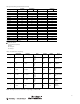
Bulletin Numbers Voltage Supply Description
60
-
1600
B
120
VAC
50/60
Hz
Open
Type
60
-
1610
B
NEMA 1
Enc
l
osu
r
e
60
-
1601
B
230
VAC
50/60
Hz
Open
Type
60
-
1611
B
NEMA 1
Enc
l
osu
r
e
For NEMA 3, 4, 12, and 13; order open type
base
and 61--4090
enclosu
r
e
.
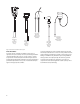
Bulletin Number
Description
Rods or
Wires Used
61
B
D1
-
1000
Probe fitting
w
it
h
rubber
cap
1
61
L
F1
-
1000
Probe fitting in
cas
t
enclosu
r
e
61
L
F1
-
1000
M
61
LJ
2
-
1000
Two probe fittings i
n
cast
enc
l
osu
r
e
2
61
LJ
2
-
1000
M
Note
: 61 Series probe fittings require suitable Series
64
probe tips and probe rod or suspension wires shown
be
l
ow
.
63
G
H1
-
1000
Special sanitary
p
r
obe
with
3 ft
(0.91 m)
p
r
obe
rod(s) supplied
w
ith
10 ft
(3 m)
cable
and
separable
connecto
r
1
63
G
H2
-
1000
2
63
G
J
1
-
1000
1
63
G
J
2
-
1000
2
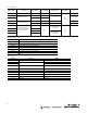
Bulletin Number
Description
64CR1-
1000
Probe Tip and
1
/
4 in.
dia. x
12 in.
(0.3 m) Probe
Rod
64CR1-
1001
Probe Tip and
1
/
4 in.
dia. x
24 in.
(0.61 m) Probe
Rod
64CR1-
1002
Probe Tip and
1
/
4 in.
dia. x
36 in.
(0.91 m) Probe
Rod
64CR1-
1003
Probe Tip and
1
/
4 in.
dia. x
48 in.
(1.22 m) Probe
Rod
64CR1-
1004
Probe Tip and
1
/
4 in.
dia. x
72 in.
(1.83 m) Probe
Rod
64CR1-
1005
Probe Tip and
1
/
4 in.
dia. x
96 in.
(2.44 m) Probe
Rod
64CR1-
1006
Probe Tip and
1
/
4 in.
dia. x
120 in.
(3 m) Probe
Rod
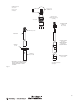
I
n
s
t
a
ll
a
t
i
on
The
c
on
tr
o
l
point
for liquid
le
v
e
l
is
the point at which the
liquid
makes
or
breaks contact
with
the probe
tip
and
is
determined
by
the length
of
th
e
probe rod. Rods may be ordered
to
size,
or
may be supplied longer
th
a
n required and cut
to
the
d
e
s
ir
e
d
length. One end
of
the rod
is
threaded
for
connection
to
the probe
fitting.
The unthreaded (cut) end
should be in
s
e
r
te
d
in
the probe
tip
and held
by
means
of
a set
s
c
r
e
w
.
For deep
w
e
ll
and other long probe applications over 10 ft
(3 m),
s
u
s
p
e
n
s
io
n
wires and tips should be installed. Standard probe
tip
613288,
is
used
with
a
ll
probe rods.
S
p
e
c
ia
l
probe
tip
61--3284
with
in
s
u
la
tin
g
sleeve,
is
u
s
e
d
w
i
t
h
s
uspens
i
on
w
i
r
e.
The probe rod
or
suspension
w
ir
e
adaptor 61--3285
is
connected
to
th
e
probe
fitting
as
f
o
llo
w
s
:
61 Series
f
ittin
g
s
have a 1/4--20
f
e
m
a
le
thread
to
receive the 1/4--20
m
a
le
thread
of
the probe rod
or
suspension
w
ir
e
a
d
a
p
to
r
.
When the long probe
of
any multiple probe assembly
is
over
30 in.
(0.76m),
a
T
e
f
lo
n
in
s
u
la
tin
g
spacer 31--224,
is fitted
over the short probe
rod
immediately above the probe
tip to
prevent the rods
from
touching.
For
suspension
w
ir
e
assemblies, an in
s
u
la
tin
g
sleeve
fits
over the probe
tip to
prevent
it from
touching other
s
u
r
f
a
c
e
s
.
Series 63 sanitary probes
for
dairy and
f
ood
in
du
s
try
applications are
m
a
d
e
for
s
p
e
c
ia
l
sanitary
f
ittin
g
s
.
The probe insulator
is
made
to fit
a #15
union
f
e
rr
u
le
and
to
be secured
with
a #13H union nut. The
f
e
rr
u
le
and
nut
a
r
e
supplied
by
the customer and are soldered, brazed,
or
otherwise
s
e
c
u
r
e
d b
e
f
o
r
e
insertion
of
the probe assembly. Probes 63GH1 and 63GH2
f
it
1--1/2 in.
f
e
rr
u
le
,
while
probes 63GJ1 and 63GJ2
fit
a
2 in.
f
e
rr
u
le
.
All
Series
63
probe rods are
3 ft
(0.91 m) long and are
to
be cut
to
length on
the
job.
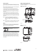
Mounting
The 13DJ3 controls may be mounted
in
any po
s
itio
n
on a sturdy
w
a
ll,
p
a
r
titio
n, p
a
n
e
l
board, bracket,
or
s
imilar
support.
While
the
NEMA
enclosure
is
being mounted, the c
on
tr
o
l
base should be stored
in
a
s
a
f
e
place
to
a
v
o
id
moisture and
m
e
c
h
a
n
ic
a
l
d
a
m
a
g
e
.
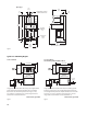
The enclosure mounting hole dimensions are shown on
page 12
and
s
h
ee
t
metal, wood
or
machine screws, bolts,
or
s
imilar
fas
te
n
e
r
s
may be
u
s
e
d.
When the housing has been securely
f
a
s
te
n
e
d,
connect the cables
or
conduits
to
the housing
in
the knock out holes provided and replace
th
e
c
on
tr
o
l
b
a
s
e
.
The
wiring
between the
c
on
tr
o
l
and the probes should not exceed
th
e
lengths listed b
e
lo
w
.
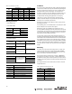
Table 8:
Maximum Recommended Cable
L
e
ng
t
h
Range
Cable Length
1
2000 ft
(
609
.6 m)
2
1000 ft
(
304
.8 m)
3
500 ft
(
152
.4 m)
4
2000 ft
(
609
.6 m)
5
2000 ft
(
609
.6 m)
6
150 ft
(
45
.7 m)