
Instruction Manual

Encoder Data
Encoders are factory aligned and must not be adjusted outside the factory.
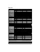
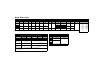
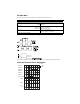
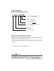
Encoder Data Waveforms Outputs
Waveforms result from clockwise rotation. “Clockwise” as viewed facing the shaft extension.
Halls and Phase-to-Phase Waveforms
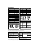
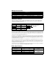
ENCODER SPECIFICATIONS
Parameter Value
Supply:
Voltage
Current
4.75 to 5.25 VDC
450 mA DC
Line Driver:
Type
Output: Logic 1
Output: Logic 0
AM 26LS31 equivalent
Sourcing 2.5 VDC @ 20 mA
Sinking 0.5 VDC @ 20mA
Line counts: Data A+, A-, B+, B-: 2000 pulse/rev
Index I+, I-: 1 pulse/rev
Hall A+, A-, B+, B-, C+, C-: 2 pulse/rev
Standard line count before quadrature
Intro
Intro
9
9
T-R
9
ELECT DEGREES
R-S
S-T
HALL C+
HALL C-
HALL B-
HALL A+
HALL B+
HALL A-
TTL LEVEL
S
LOGIC 1
LOGIC
0