Allen-Bradley Y-Series Brushless Servo Motor Manual
IntroProduct Notice Use of Motors Servo motors are intended to drive machinery. As such, they must be part of a controlled system that includes a transistorized electronic amplifier. They are not intended for direct connection to the power supply or for use with thyristor drives. Instructions in the amplifier and control system manuals must be observed; this document does not replace those instructions.
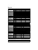
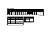
Motor Data MOTOR MODEL Rotor Moment of Inertia Brake Motors Rotor Moment of Inertia Motor Weight: Net Shipping Brake Motor Weight: Net Shipping Damping Friction Torque Max. Operating Speed Y-1002-1 Y-1002-2 Y-1003-1 Y-1003-2 MECHANICAL DATA (1) Y-2006-1 Y-2006-2 0.000015 kg-m2 0.0000031 0.0000031 0.0000051 0.0000051 0.000015 lb-in-s2 0.000027 0.000027 0.000045 0.000045 0.00013 0.00013 kg-m2 0.0000039 0.0000039 0.0000059 0.0000059 0.000020 0.
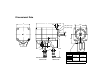
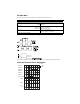
Dimensional Data Intro L P AH BE BB AK BP (3023 only) EP (3023 only) U AB LD BF and AJ LA LB LE LC CAB W2 W1 LD SHAFT END THREADED HOLE Motor Thread Thread/Depth Y-1002 NA NA M5 x 0.80 12.00/0.5 Y-1003 MOTOR ENCODER CONNECTOR Y-2006 MOTOR POWER CONNECTOR Y-2012 Y-3023 NOTE: Motors are manufactured to millimeter dimensions. Inch dimensions are approximate conversions.
Motor Dimensions MOTOR DIMENSIONS BP EP Motor Model AB AH AJ AK BB BE BF L L Brake P U CAB mm/in mm/in mm/in mm/in mm/in mm/in mm/in mm/in mm/in mm/in mm/in mm/in mm/in mm/in Y-1002 30/1.2 25/1.0 (1) 46/1.8 30/1.2 (2) 2.5/0.10 5/0.20 4.5/0.18 - - 70.0/2.8 (3) 108.5/4.27 (3) 40/1.6 8/0.3 (4) 1000/39.4 (8) 88.0/3.5 (3) 126.5/4.98 (3) 60/2.4 14/0.5 (7) 80/3.1 16/0.6 (7) Y-1003 Y-2006 41/1.6 30/1.2 (1) 70/2.8 50/2.0 (5) 3.0/0.12 6/0.24 5.5/0.22 95.5/3.
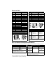
Connector Data All Y-Series Motors - Encoder Connector All Y-Series Motors - Power Connector Pin Signal Wire color Pin Signal 1 to 8 - - 1 PHASE R Wire color RED 9 A+ PURPLE 2 PHASE S BLACK 10 A- GREEN 3 PHASE T WHITE 11 B+ BLUE 4 - - 12 B- BROWN 5 GROUND GREEN/YELLOW 13 I+ WHITE 6 - - 14 I- YELLOW 7 BRAKE + (option) YELLOW 15 HALL A+ GREEN/BLACK 8 - - 16 HALL A- PURPLE/BLACK 9 BRAKE - (option) YELLOW 17 HALL B+ BLUE/BLACK 18 HALL B- BROWN/BL
Mating Connector Kit CONNECTOR KIT Item Part Number Encoder and Power Connector Kit 9106-0066 Kit includes connector housing, pins and backshell with clamp to mate with Y-Series motor connectors. Connector Housing Socket (Qty Pins included) Backshell Encoder AMP 205839-3 AMP 6-66504-0 (18) AMP206070-1 Power AMP 206708-1 AMP 66360-3 (8) AMP207008-1 Load Force Ratings Motors are capable of carrying a radial or axial load.
Encoder Data Encoders are factory aligned and must not be adjusted outside the factory. ENCODER SPECIFICATIONS Parameter Value Supply: Voltage 4.75 to 5.25 VDC Current 450 mA DC Line Driver: Type AM 26LS31 equivalent Output: Logic 1 Sourcing 2.5 VDC @ 20 mA Output: Logic 0 Sinking 0.
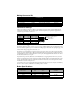
Motor Installation Observe the following installation guidelines and those in the Product Notice: ! WARNING: Motors and linkages must be securely mounted for a system to be operational. Disassembled equipment should be appropriately identified (tagged-out) and access to electrical power restricted (locked-out). Failure to observe these safety procedures could result in personal injury and damage to equipment. 1. Do not run motors that are not properly mounted.
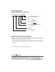
Product Information Motor Part Number Identification Y - 2012 - 2 - H 00 AA FACTORY DESIGNATED SPECIAL OPTIONS AA = STANDARD FLANGE OPTIONS 00 = 04 = STANDARD 24 VDC BRAKE OPTICAL ENCODER LINE COUNT H = 2000 (STANDARD) MOTOR WINDING VOLTAGE DESIGNATOR 1 = 115 VAC 2 = 230 VAC FRAME SIZE SERIES DESIGNATOR Y = Light Industrial Disposal or Warranty Return of Motors Motors may contain environmentally regulated materials, such as lead solder and circuit boards.