
Instruction Manual

304 Variables and Flags Assignment and Request Commands • Inputs – Analog and Digital
Publication 1398-PM601A-EN-P — October 2000
HOST MODE
Inputs – Analog and Digital
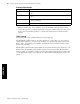
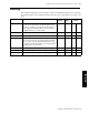
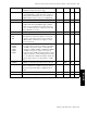
The commands in this table cover all digital and analog inputs including inputs located on optional I/O
Expansion Cards.
Command Description Flag/
Variable
Read/
Write
Personality
Module
ADC1 Analog input 1 in volts (option card required). V R N
ADC2 Analog input 2 in volts (option card required). V R N
ADC3 Analog input 3 in volts (option card required). V R N
ADC4 Analog input 4 in volts (option card required). V R N
ADC5 Analog input 5 in volts (option card required). V R N
AFEED TRUE to enable ADC1 for analog feedrate. F R/W Y
DBNCE Debounce time (mS). byte R/W Y
I1…I48 Digital inputs status. F R N
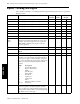
IB1
IB2
IB3
These read-only variables access the status of the digi-
tal inputs as an entire block. Bits 0..15 correspond to
inputs 1..16. If an I/O expansion card is present, the
IB2 and IB3 commands access inputs 17..32 and
33..48 respectively.
word R N
PACTIVE TRUE for active closed PAUSE switch. F R/W Y
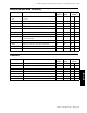
PGMSEL Number of program select lines. Input 16 is always the
MSB.
byte R/W Y
PSELECT TRUE to enable running from program switch. F R/W Y
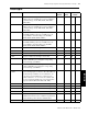
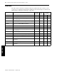
SWINP This word variable represents a bit map indicating
whether or not various inputs are assigned. Bits 0..15
correspond to inputs 1..16 and reflect the assignment
(1) or non-assignment (0) of fixed inputs. Unused bits
that are not associated with fixed inputs should be
cleared.
BIT Description
0 Forward Travel Limit
1 Reverse Travel Limit
2 Enable
3Start Program
4 Home Switch
5Start Home
6Jog Reverse
7Jog Forward
8Pause
9 Emergency Return to Position
10..15 (Reserved)
word R/W Y
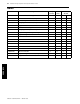
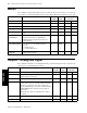
XINP If the STOP input is assigned, the single bit set in the
word corresponds to the input assigned to the func-
tion. A value of zero indicates that the function is not
assigned. Care must be taken to avoid assigning multi-
ple functions to the same input.
word R/W Y