
Instruction Manual

Inputs and Outputs • General Purpose Outputs 91
Publication 1398-PM601A-EN-P — October 2000
I/O
Propagation Delay
The maximum time delay between the interrupt input turning ON and the position data being captured
is 50 microseconds for the software interrupts. The hardware latch captures the position of one encoder
in 1.5 microseconds.
When an Interrupt Turns ON
If the interrupt is enabled, the positions of encoder 1 and encoder 2 are captured and stored in the appro-
priate system variable. See the table below.
When an Interrupt Turns OFF
This edge is ignored by the ULTRA Plus or IQ.
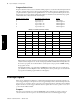
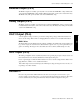
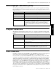
Associated Input Interrupt Instruction, Variables and Flags
General Purpose Outputs
Any digital output 1 through 8 that is not assigned a dedicated function may be used as a general pur-
pose output. Digital outputs are set once every velocity loop update (1mS). When a program instruction
such as,
O1 = ON;Turn ON Output 1
is executed, a flag is set, not the physical output. Then, once every velocity loop update (1mS), the out-
puts are set according to the state of the internal flags.
General purpose outputs can be programmed to turn ON, turn OFF or remain unchanged when a pro-
gram stops executing for any reason. Refer to Part 2 • IQ Master Environment, Parameter menu,
Default Outputs, for more detailed information.
Name
Description
1
1.
Refer to Part 5 • Language Reference for detailed information.
FI1 Flag to indicate that interrupt 1 has occurred
FI2 Flag to indicate that interrupt 2 has occurred
I1P1 Position from encoder 1, captured when interrupt 1 occurred
I1P2 Position from encoder 2, captured when interrupt 1 occurred
I2P1 Position from encoder 1, captured when interrupt 2 occurred
I2P2 Position from encoder 2, captured when interrupt 2 occurred
INT1 Enable and disable interrupt 1
INT2 Enable and disable interrupt 2
LPOS Position from encoder 1 or 2 captured in hardware when interrupt 1 occurred
SINT2 Force an interrupt 2 with a software instruction.