Allen-Bradley N-Series Brushless Servo Motor Manual
IntroProduct Notice Use of Motors Servo motors are intended to drive machinery. As such, they must be part of a controlled system that includes a transistorized electronic amplifier. They are not intended for direct connection to the power supply or for use with thyristor drives. Instructions in the amplifier and control system manuals must be observed; this document does not replace those instructions.
Motor Data MOTOR Rotor Moment of Inertia Rotor Moment of Inertia Motors W/Brake N-2302-1 N-2304-1 N-3406-2 N-3412-2 MECHANICAL DATA (1) N-4214-2 N-4220-2 0.00035 kg-m2 0.000009 0.00002 0.00008 0.00015 0.00024 lb-in-s2 0.00008 0.00016 0.0007 0.0013 0.0021 0.0031 kg-m2 0.000018 0.000032 0.000122 0.000202 0.000210 0.000320 0.00108 0.00179 0.00186 0.00283 2.6/5.7 3.5/7.7 3.0/6.6 4.0/8.8 3.4/7.5 4.3/9.5 3.9/8.6 4.8/10.6 0.13 0.19 1.1 1.7 0.26 0.34 2.3 3.
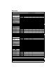
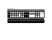
Dimensional Data Intro L U BF DIA HOLES AJ DIA CIRCLE N-2300 AB BB BE AH SHAFT END PLAY UNDER LOAD Maximum end play (All Motors) Direction mm/in ---> A 0.127/ 0.005 <--- B 0.025/ 0.001 brake option connector Load (Kg/Lb) AK P power connector 3.8/10 L Note: End play and load are measured in inches and pounds. Metric measurements are approximate conversions from inches and pounds.
Motor Dimensions MOTOR DIMENSIONS L L Brake Motor AB AH AJ AK BB BE BF S U XD Model mm/in mm/in mm/in mm/in mm/in mm/in mm/in mm/in mm/in mm/in mm/in mm/in N-2302 70/2.75 21/0.81 (1) 67/2.63 38/1.50 (2) 2/.09 7/0.28 5/0.21 118/4.63 161/6.32 NA 6/.25 (3) NA 156/6.13 199/7.82 3.2 X 3.2 /0.125 X 0.125 (5) 13/.5 (3) 19/0.75 (6) 4.8 X 4.8 /0.1875 X 0.1875 (5) 16/.63 (3) 24/0.94 (6) 19/.75 (3) 38/1.50 (6) N-2304 N-3406 63/2.48 30/1.19 (1) 98/3.88 73/2.88 (4) 3/.
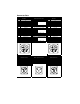
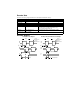
Connector Data Pin NEMA 23-Series Encoder Signal A B C D E F A+ AB+ BI+ I- G GROUND H J K L M N Open 5 VDC 5 VDC COMMON COMMON Open P Open R S T U V THERMOSTAT+ THERMOSTATHALL A HALL B HALL C Pin A B C D E NEMA 23-Series Power Connector Signal PHASE R PHASE S PHASE T GROUND Open ITT Cannon Connectors Power Connector P/Ns N-2300 KPSE02E14-5P-A71 N-3400 N-4200 N-5600 Connectors require1/4 turn to seal NEMA 34, 42 & 56-Series Encoder Pin Signal A B C D E F A+ AB+ BI+ I- Encoder Connector P/Ns
Encoder Data Encoders are factory aligned and must not be adjusted outside the factory. N-2300 ENCODER SPECIFICATIONS N-3400, N-4200 and N-5600 Line Count Supply Voltage Supply Current Line Driver Line Driver Output 1000 (1) (2) 5 VDC 175 mA max. LM339 TTL 2000 (1) 5 VDC 300 mA max. 26LS31 A, B, I signals: Logic 1 =2.5 VDC min @ 20 mA DC source, Logic 0 = 0.5 VDC max @ 20 mA DC sink. HALL signals: Logic 1 = 3.5 VDC min @ 1mA DC source, Logic 0 = 0.5 VDC max @ 5mA DC sink.
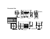
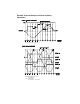
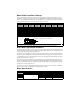
Encoder Phase-to-Neutral and Phase-to-Phase Waveforms NOTE: N-3400, N-4200 and N-5600 only NOTE: Hall and ABS signals are in electrical degrees. For 4 pole commutation, 360° mechanical = 720° electrical.
Options: Connectors and Shaft Seals An environmentally sealed package may be formed when an N-Series motor is coupled with sealed cable assemblies and shaft seals. Factory manufactured power cables and encoder cables are available in standard cable lengths of 10, 25, 50, 75 and 100 feet (3, 7.6, 15, 23 and 30 meters). Factory cables provide environmental sealing and shield termination.
Motor Radial Load Force Ratings Motors are capable of carrying an axial load in most applications. The following table provides guidelines for 20,000 hour bearing life with a specified radial load applied to the center of the shaft. Please consult with Reliance Motion Control regarding loads, operating speeds and bearing life in your particular application to ensure the proper selection of motors.
Motor Installation Observe the following installation guidelines and those in the Product Notice: ! WARNING: Motors and linkages must be securely mounted for a system to be operational. Disassembled equipment should be appropriately identified (tagged-out) and access to electrical power restricted (locked-out). Failure to observe these safety procedures could result in personal injury and damage to equipment. 1. Do not run motors that are not properly mounted.
Product Information Motor Part Number Identification N - 42 14 - 2 - H 00 AA FACTORY DESIGNATED SPECIAL OPTIONS AA = STANDARD FLANGE OPTIONS 00 = 04 = STANDARD 24 VDC BRAKE ENCODER LINE COUNT F = 1000 (N-2300 STANDARD) H = 2000 (N-3400 thru N-5600 STANDARD) K = 5000 MOTOR WINDING VOLTAGE DESIGNATOR 1 = 115 VAC 2 = 230 VAC CONTINUOUS TORQUE CAPABILITY (LB-IN) FRAME SIZE SERIES DESIGNATOR N = NEMA FRAME STYLE NOTE: OPTIONS NOT AVAILABLE ON ALL SIZES Disposal or Warranty Return of Motors Motors may contain