Allen-Bradley F-Series Brushless Servo Motor Manual
IntroProduct Notice Use of Motors Servo motors are intended to drive machinery. As such, they must be part of a controlled system that includes a transistorized electronic amplifier. They are not intended for direct connection to the power supply or for use with thyristor drives. Instructions in the amplifier and control system manuals must be observed; this document does not replace those instructions.
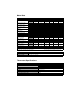
Motor Data MOTOR MODEL F-4030 Rotor Moment of Inertia Rotor Moment of Inertia Brake Motors Motor Shipping Weight Motor Shipping Weight Brake Motors Damping Friction Torque Max. Operating Speed F-4050 F-4075 F-6100 MECHANICAL DATA (1) F-6200 F-6300 kg-m2 .0010 .0021 .0032 .0064 .0107 .0162 lb-in-s2 .009 .019 .029 .057 .095 .144 kg-m2 .0011 .0022 .0033 .007 .011 .017 lb-in-s2 kg lb kg lb Nm/krpm lb-in/krpm Nm lb-in rpm .010 .020 .030 .061 .098 .147 10.4 23 12.5 27.6 .06 .5 .
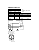
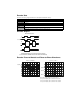
Dimensional Data Intro 2 EYE BOLTS INSTALLED ON F-6100, 6200, AND 6300 MOTORS ONLY. L AH BF DIA HOLES - AJ DIA BOLT CIRCLE BB XD S U AK AB BRAKE OPTION SHAFT END THREADED HOLE SHAFT END PLAY UNDER LOAD Maximum End Play (All Motors) Direction →A ←B SHAFT END THREADED HOLE Load Applied to Shaft mm/in Motor Series Kg/Lb Motor Series Thread Thread/Depth 0.025/0.001 F-4000 9.07/20.0 F-4000 M6 x 1.0mm 15mm/.59in 0.254/0.010 F-6000 22.68/50.0 F-6000 M8 x 1.25mm 20mm//.
Motor Dimensions MOTOR DIMENSIONS EP L AB AH AJ AK BB BF Motor Model mm/in mm/in mm/in mm/in mm/in mm/in mm/in F-4030 102/4.02 50/1.97 (1) 145/5.71 110/4.33 (2) 3/.12 (3) 10/.39 (4) 22.2/.875 (6) F-4050 F-4075 F-6100 F-6200 131/5.16 80/3.15 (1) 200/7.87 114.3/4.50 (2) 4/.16 (3) 13.5/53 (5) 36.5/1.438 (7) F-6300 L with Brake P S U XD mm/in mm/in mm/in mm/in mm/in mm/in 194/7.64 257/10.12 127/5.00 6x6/.24x.24 19/.75 (8) 38/1.49 272/10.71 335/13.19 350/13.
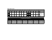
Connector Data All F-Series Motors Encoder Signal Pin All F-Series Motors Power Signal Pin A A+ A R B A– B S C B+ C T D B– D MOTOR CASE E I+ F I– G ENCODER CASE H ABS J +5VDC K +5VDC L COM M COM N HALL B P HALL C R TS+ S TS– T HALL A A C B P0002 Brake (option) Signal Pin A BR+ B BR– B M C N T L D A P D K S E R J B A F H G P0001 P0003 MIL-SPEC part numbers F-4000 F-6000 Power MS3102A-20-4P Power MS3102A-24-22P MIL-SPEC part numbers All
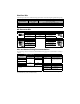
Shaft Seal Kits Shaft seals protect the motor and its bearings against dust or water entering through the shaft opening. MOTOR SEAL KITS MOTOR SERIES SIZE (O Dia x I Dia x Width) PART NUMBER F-4000 0041-5060 1.437” x 0.875” x 0.25” (36mm x 22mm x 6mm) F-6000 0041-5061 2.125” x 1.438” x 0.31” (54mm x 37mm x 8mm) NOTE: Shaft seals are manufactured to inch dimensions. Millimeter dimensions are conversions from inches. Shaft seals require a lubricant to reduce wear.
F-4000 Series NEMA 56C Motors Dimensions Without Brake Motors in/mm With Brake in/mm F-4030 NEMA 56C 7.64/194 10.12/257 F-4050 NEMA 56C 10.71/272 13.19/335 F-4075 NEMA 56C 13.79/350 16.26/413 Note: NEMA 56C motors are manufactured to inch dimensions. Millimeter dimensions are approximate conversions from inches.
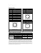
Encoder Data Encoders are factory aligned and must not be adjusted outside the factory. ENCODER SPECIFICATIONS Line Count Supply Voltage Supply Current Line Driver Line Driver Output Index Pulse 2000 (1) 5 VDC 250 mA max. 26LS31 TTL F-2000 and F-3000 Series when key faces 180o±10 away from the connectors F-4000, F-6000 and F-8000 Series when key faces the connectors (0o±10) (1) Standard line count before quadrature Encoder Outputs ENCODER OUTPUT 1 A 0 A 90°±22.
Motor Radial Load Force Ratings Motors are capable of carrying an axial load in most applications. The following table provides guidelines for 20,000 hour bearing life with a specified radial load applied to the center of the shaft. Please consult with Rockwell Automation regarding loads, operating speeds and bearing life in your particular application to ensure the proper selection of motors.
Motor Installation Observe the following installation guidelines and those in the Product Notice: ! ATTENTION: Motors and linkages must be securely mounted for a system to be operational. Disassembled equipment should be appropriately identified (tagged-out) and access to electrical power restricted (lockedout). Failure to observe these safety procedures could result in personal injury and damage to equipment. 1. Do not run motors that are not properly mounted.
Product Information Motor Part Number Identification F - 4030 - Q- H 00 AA FACTORY DESIGNATED SPECIAL OPTIONS AA = STANDARD FLANGE AN = NEMA 56C FLANGE OPTIONS 00 = STANDARD 01 = 90 VDC BRAKE 04 = 24 VDC BRAKE OPTICAL ENCODER LINE COUNT F H J K L M N = = = = = = = 1000 2000 (STANDARD) 2500 5000 F-Series 00 3000 2000 MOTOR WINDING KE VOLTAGE DESIGNATOR NOTE: Special order windings available FRAME SIZE SERIES DESIGNATOR F = Medium inertia Disposal or Warranty Return of Motors Motors may contain environ