
User Manual


Publication 1398-5.0 – October 1998
Interfaces 6-31
6Interfaces
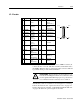
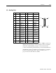
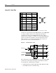
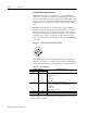
J3 – Auxiliary Port
J3 is a 26 pin female mini-D ribbon connector (AMP 2-178238-4). It
duplicates the first 26 pins of J1, the Controller connector, which are
discussed in detail beginning on page 6-1. Contact between the
connector shell and the grounded chassis provides shield termination.
Allen-Bradley cables are available in various lengths for connecting
between J3 and an auxiliary unit. “Options and Accessories” on
page A-1 lists the cables that are available.
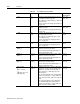
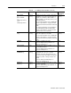
Pin Signal Description Pin Signal Description
1 +5VDC Encoder +5V
DC
14 AX+ Auxiliary
Channel A+
2 ECOM Encoder
Common
15 AX- Auxiliary
Channel A-
3 +5VDC Encoder +5V
DC
16 BX+ Auxiliary
Channel B+
4 ECOM Encoder
Common
17 BX- Auxiliary
Channel B-
5 +24VDC Isolated +24
VDC
18 IX+ Auxiliary
Channel I+
6 24VCOM Isolated 24V
Common
19 IX- Auxiliary
Channel I-
7 AOUT+ Motor Output
Channel A+
20 ENABLE ENABLE
8 AOUT- Motor Output
Channel A-
21 RESET FAULT
RESET
9 BOUT+ Motor Output
Channel B+
22 COMMAND+ Analog
Command+
10 BOUT- Motor Output
Channel B-
23 COMMAND- Analog
Command-
11 IOUT+ Motor Output
Channel I+
24 READY+ READY+
12 IOUT- Motor Output
Channel I-
25 READY- READY-
13 24VCOM Isolated 24V
Common
26 +24VDC +Isolated +24
VDC
pin 13
pin 14
pin 26
pin 1