
User Manual


Publication 1398-5.0 – October 1998
Interfaces 6-29
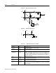
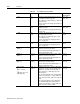
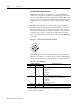
HALL A J2-13 Hall Effect A sensor logic level input. Internally pulled up to +5VDC
through a 1 kOhm resistor.
The input signal interfaces to both a differential and single-ended
Hall effect sensor, using either a TTL level signal or open collector
signal. A differential output connects only the (+) output to the
drive.
Software determines when the hall effect sensors are in an illegal
state.
HALL B J2-14 Hall Effect B sensor logic level input. Internally pulled up to +5VDC
through a 1 kOhm resistor.
The input signal interfaces to both a differential and single-ended
Hall effect sensor, using either a TTL level signal or open collector
signal. A differential output connects only the (+) output to the
drive.
Software determines when the hall effect sensors are in an illegal
state.
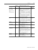
HALL C J2-15 Hall Effect C sensor logic level input. Internally pulled up to +5VDC
through a 1 kOhm resistor.
The input signal interfaces to both a differential and single-ended
Hall effect sensor, using either a TTL level signal or open collector
signal. A differential output connects only the (+) output to the
drive.
Software determines when the hall effect sensors are in an illegal
state.
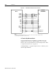
ABS J2-16 Absolute Position used on Allen-Bradley motors for commutation.
J2-17
J2-18
Reserved.
TS (+)
TS(-)
J2-19
J2-20
Thermal Switch (+) and Thermal Switch (-) are thermostat inputs,
with an open condition indicating a motor overtemperature fault.
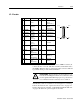
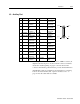
Table 6.22: J2- Motor Encoder Connector Pin-Outs (continued)
Motor Encoder Pin Number Description