
User Manual


Publication 1398-5.0 – October 1998
Interfaces 6-27
6Interfaces
J2 – Encoder
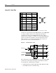
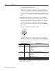
J2 is a 20 pin female mini-D ribbon connector (AMP 2-178238-2). It
connects the motor encoder, hall effect switches, and the thermostat to
the ULTRA 200 Series drive. Contact between the connector shell and
a grounded chassis provides shield termination.
Allen-Bradley cables are available in various lengths for connecting
between J2 and an encoder. “Options and Accessories” on page A-1
lists the cables that are available. “J2 Terminal Strip/Breakout Board”
on page 6-30 details the optional signal extension kit.
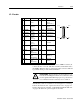
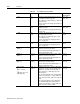
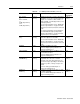
Pin Signal Description Pin Signal Description
1 EPWR Encoder
Power
11 I (+) Motor Encoder
Input
Channel I(+)
2 ECOM Encoder
Common
12 I (-) Motor Encoder
Input
Channel I(-)
3 EPWR Encoder
Power
13 HALL A Hall Effect A
4 ECOM Encoder
Common
14 HALL B Hall Effect B
5 SENSE
(+)
Encoder
Power
Sense (+)
15 HALL C Hall Effect C
6 SENSE
(-)
Encoder
Power
Sense (-)
16 ABS Absolute
Position
7 A (+) Motor Encoder
Input
Channel A(+)
17 Reserved
8 A (-) Motor Encoder
Input
Channel A(-)
18 Reserved
9 B (+) Motor Encoder
Input
Channel B(+)
19 TS(+) Thermal
Switch (+)
10 B (-) Motor Encoder
Input
Channel B(-)
20 TS(-) Thermal
Switch (-)
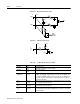
pin 10
pin 11
pin 20
pin 1
!
Intro
ATTENTION: Ensure that the encoder signals are con-
nected as shown in Figure 6.36. Incorrect connection of the
encoder signals will result in improper rotor position, incor-
rect commutation and/or a runaway motor condition.